Toyota Tacoma (2015-2018) Service Manual: Parking Brake Lever
Components
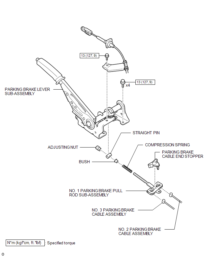
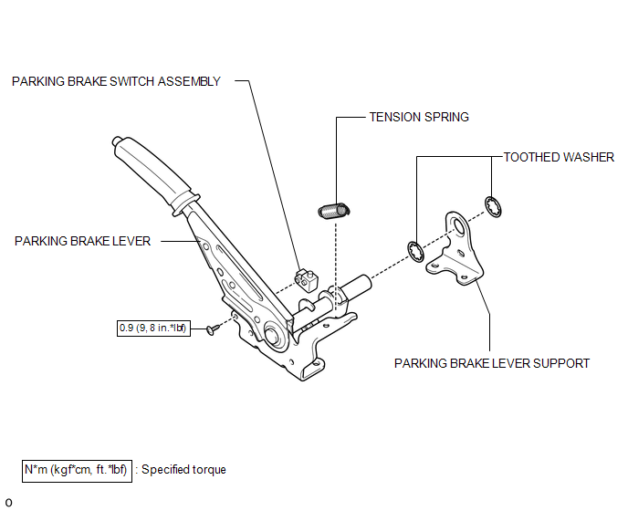
COMPONENTS
ILLUSTRATION
ILLUSTRATION
Installation
INSTALLATION
PROCEDURE
1. INSTALL PARKING BRAKE SWITCH ASSEMBLY
.gif)
2. INSTALL PARKING BRAKE LEVER SUB-ASSEMBLY
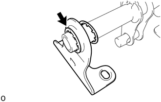
(a) Install the 2 toothed washers and parking brake lever support to the parking brake lever.
(b) Install the tension spring to the parking brake lever.
(c) Install the parking brake lever sub-assembly with the 4 bolts.
Torque:
13 N·m {127 kgf·cm, 9 ft·lbf}
(d) Engage the 2 clamps to install the wire harness from the parking brake lever sub-assembly.
(e) Install the straight pin to the parking brake lever.
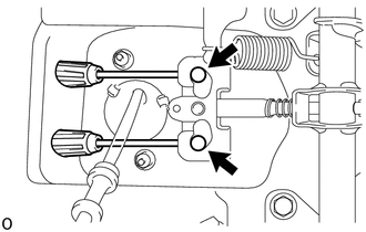
(f) Connect the No. 2 parking brake cable and No. 3 parking brake cable to the No. 1 parking brake pull rod.
(g) Engage the 2 claws to install the parking brake cable end stopper.
(h) Install the bush, compression spring and No. 1 parking brake pull rod to the parking brake lever with the adjusting nut.
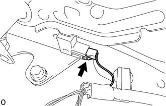
(i) Connect the parking brake switch connector.
3. CONNECT TRANSMISSION CONTROL CABLE ASSEMBLY
4. INSPECT PARKING BRAKE LEVER TRAVEL
5. ADJUST PARKING BRAKE LEVER TRAVEL
6. INSTALL VOLTAGE INVERTER ASSEMBLY
(See page )
Removal
REMOVAL
PROCEDURE
1. REMOVE VOLTAGE INVERTER ASSEMBLY
(See page .gif) )
)
2. DISCONNECT TRANSMISSION CONTROL CABLE ASSEMBLY
3. REMOVE PARKING BRAKE LEVER SUB-ASSEMBLY
(a) Release the parking brake lever.
|
(b) Disconnect the parking brake switch connector. |
|
|
(c) Remove the adjusting nut. |
|
.png)
|
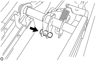
(d) Disengage the 2 claws to remove the parking brake cable end stopper. |
|
.png)
|
(e) Disconnect the No. 2 parking brake cable assembly and No. 3 parking brake cable assembly from the No. 1 parking brake pull rod. |
|
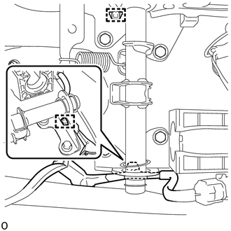
(f) Remove the No. 1 parking brake pull rod, bush and compression spring from the parking brake lever.
|
(g) Remove the straight pin from the parking brake lever. |
|
|
(h) Disengage the 2 clamps to separate the wire harness from the parking brake lever sub-assembly. |
|
|
(i) Remove the 4 bolts and parking brake lever. |
|
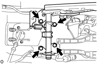
|
(j) Remove the tension spring from the parking brake lever. |
|
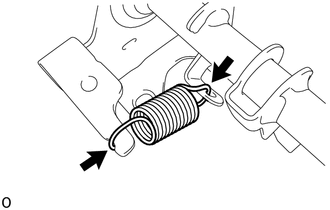
|
(k) Remove the 2 toothed washers and parking brake lever support from the parking brake lever. |
|
4. REMOVE PARKING BRAKE SWITCH ASSEMBLY
 Parking Brake Cable
Components
COMPONENTS
ILLUSTRATION
Removal
REMOVAL
PROCEDURE
1. DISCONNECT NO. 2 PARKING BRAKE SHOE ASSEMBLY WITH PARKING BRAKE SHOE LEVER
(See page )
2. REMOVE VOLTAGE INVERTER ASSEMBL ...
 Parking Brake Switch
Components
COMPONENTS
ILLUSTRATION
Inspection
INSPECTION
PROCEDURE
1. INSPECT PARKING BRAKE SWITCH ASSEMBLY
(a) Check the resistance.
(1) Measure the resistance according to the value(s) ...
Other materials:
Precaution
PRECAUTION
1. BASIC REPAIR HINT
(a) HINTS ON OPERATIONS
1
Attire
Always wear a clean uniform.
A hat and safety shoes must be worn.
2
Vehicle protection
Prepare a grille cover, fe ...
System Diagram
SYSTEM DIAGRAM
Communication Table
Sender
Receiver
Signal
Line
ECM
Combination Meter Assembly
Cruise main indicator light signal
CAN
Skid Control ECU
ECM
Vehicle st ...
Manual Transmission Unit
Components
COMPONENTS
ILLUSTRATION
ILLUSTRATION
*1
SHIFT DETENT BALL PLUG
*2
SHIFT DETENT BALL COMPRESSION SPRING
*3
MANUAL TRANSMISSION FILLER PLUG
*4
SHAFT DETENT BALL
*5
...
