Toyota Tacoma (2015-2018) Service Manual: On-vehicle Inspection
ON-VEHICLE INSPECTION
PROCEDURE
1. INSPECT AIR CONDITIONER PRESSURE SENSOR (for Automatic Air Conditioning System)
(a) Check the wire harness.
(1) Disconnect the A34 air conditioner pressure sensor connector.
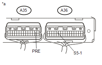
(2) Disconnect the A35 and A36 air conditioning amplifier assembly connector.
|
(3) Measure the resistance according to the value(s) in the table below. Text in Illustration
Standard Resistance:
If the resistance is not as specified, repair the wire harness. |
|

(4) Connect the A35 and A36 air conditioning amplifier assembly connector.
|
(5) Measure the voltage according to the value(s) in the table below. Text in Illustration
Standard Voltage:
If the voltage is not as specified, repair the wire harness or replace the air conditioning amplifier assembly. |
|

(b) Check the air conditioner pressure sensor.
(1) Install a manifold gauge set.
(2) Connect the A34 air conditioner pressure sensor connector.
(3) Warm up the engine.
(4) A/C switch on.
|
(5) Measure the voltage according to the value(s) in the table below. Text in Illustration
Standard Voltage:
If the voltage is not as specified, replace the air conditioner pressure sensor. |
|
2. INSPECT AIR CONDITIONER PRESSURE SENSOR (for Manual Air Conditioning System)
(a) Check the wire harness.
(1) Disconnect the A34 air conditioner pressure sensor connector.
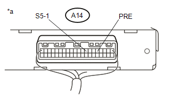
(2) Disconnect the A14 air conditioning amplifier assembly connector.
|
(3) Measure the resistance according to the value(s) in the table below. Text in Illustration
Standard Resistance:
If the resistance is not as specified, repair the wire harness. |
|

(4) Connect the A14 air conditioning amplifier assembly connector.
|
(5) Measure the voltage according to the value(s) in the table below. Text in Illustration
Standard Voltage:
If the voltage is not as specified, repair the wire harness or replace the air conditioning amplifier assembly. |
|

(b) Check the air conditioner pressure sensor.
(1) Install a manifold gauge set.
(2) Connect the A34 air conditioner pressure sensor connector.
(3) Warm up the engine.
(4) A/C switch on.
|
(5) Measure the voltage according to the value(s) in the table below. Text in Illustration
Standard Voltage:
If the voltage is not as specified, replace the air conditioner pressure sensor. |
|
 Installation
INSTALLATION
PROCEDURE
1. INSTALL AIR CONDITIONER PRESSURE SENSOR
(a) Remove the vinyl tape from the air conditioner tube and accessory assembly
and connecting part of the air conditioner pressur ...
 Removal
REMOVAL
PROCEDURE
1. REMOVE REFRIGERANT FROM REFRIGERATION SYSTEM
2. REMOVE AIR CONDITIONER PRESSURE SENSOR
(a) Disconnect the connector.
...
Other materials:
Downhill Assist Control system
The downhill assist control system helps to prevent excessive speed on steep
downhill descents.
■ System operation
The system will operate when the vehicle is traveling under 15 mph (25 km/h)
and the front-wheel drive control switch is in the L4 position.
Press the DAC switch. The ind ...
Seat Belt Buckle Switch LH Circuit Malfunction (B1656/38)
DESCRIPTION
The seat belt buckle switch LH circuit consists of the airbag sensor assembly
and the front seat inner belt assembly LH (seat belt buckle switch LH).
DTC B1655/37 is stored when a malfunction is detected in the seat belt buckle
switch LH circuit.
DTC No.
DTC ...
AUTO LSD Indicator Light does not Come ON
DESCRIPTION
The AUTO LSD does not operate even if the VSC OFF switch is pressed under the
following conditions:
The brake system is faulty.
The temperature inside the hydraulic brake booster increases and the
AUTO LSD operation is suspended.
The rear differential is locked.
...
