Toyota Tacoma (2015-2018) Service Manual: On-vehicle Inspection
ON-VEHICLE INSPECTION
PROCEDURE
1. INSPECT INDICATOR LIGHT
(a) Inspect the 4HI Indicator Light:
(1) Start the engine.
(2) Change the 4WD control switch from 2WD to 4H.
(3) Check the 4HI indicator light.
OK:
The 4HI indicator light comes on or the 4HI indicator light comes on after it is blinking.
If the result is not as specified, inspect the switch, four wheel drive control
ECU and transfer shift actuator assembly. If there is a malfunction, inspect the
switch, ECU, transfer shift actuator and A.D.D. actuator. If the system is normal,
there may be a malfunction in the CAN communication system or combination meter.
In this case, first check the CAN communication system (See page
.gif) ). Then check
the combination meter (See page
) and touch select 2- 4 and high-low system (See
page ).
). Then check
the combination meter (See page
) and touch select 2- 4 and high-low system (See
page ).
(b) Inspect the 4LO Indicator Light:
(1) Start the engine.
(2) Move the shift lever to N.
(3) Change the 4WD control switch from 2WD to 4H. Then change it from 4H to 4L after the 4HI indicator light illuminates (after 4H switch completion).
(4) Check the 4LO indicator light.
OK:
The 4LO indicator light comes on or the 4LO indicator light comes on after it is blinking.
If there is a malfunction, inspect the switch, ECU and actuator. If the system is normal, the combination meter may be malfunctioning.
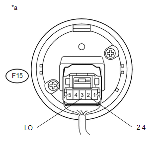
2. INSPECT TRANSFER POSITION SWITCH
(a) Remove the transfer position switch with its connector still connected (See
page ).
|
(b) Measure the voltage according to the value(s) in the table below. Standard Voltage:
|
|
 Components
COMPONENTS
ILLUSTRATION
ILLUSTRATION
...
 Removal
REMOVAL
PROCEDURE
1. REMOVE AIR CONDITIONING CONTROL ASSEMBLY (for Automatic Air Conditioning System)
(See page )
2. REMOVE INTEGRATION PANEL SUB-ASSEMBLY (for Manual Cooler System)
(See page ...
Other materials:
Parts Location
PARTS LOCATION
ILLUSTRATION
*A
for Hydraulic Brake Booster
*B
for Vacuum Brake Booster
*1
FORWARD RECOGNITION CAMERA
*2
MILLIMETER WAVE RADAR SENSOR ASSEMBLY
*3
HYDRAULIC BRA ...
Dtc Check / Clear
DTC CHECK / CLEAR
HINT:
DTCs which are stored in the ECM can be displayed on the Techstream.
The Techstream can display pending DTCs and current DTCs. Some DTCs
are not stored unless a malfunction is detected in consecutive driving cycles.
When a malfunction is detected in o ...
Dtc Check / Clear
DTC CHECK / CLEAR
1. CHECK DTC
(a) Connect the Techstream to the DLC3.
(b) Turn the ignition switch to ON.
(c) Turn the blind spot monitor main switch assembly (warning canceling switch
assembly) on.
(d) Turn the Techstream on.
(e) Enter the following menus: Body Electrical / Blind Spot Moni ...
