Toyota Tacoma (2015-2018) Service Manual: Oil Level Sensor
Components
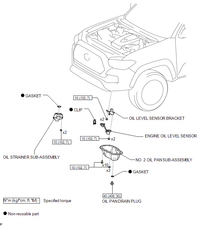
COMPONENTS
ILLUSTRATION
ILLUSTRATION
Inspection
INSPECTION
PROCEDURE
1. INSPECT ENGINE OIL LEVEL SENSOR
|
(a) Measure the resistance according to the value(s) in the table below. Standard Resistance:
If the result is not as specified, replace the engine oil level sensor. |
|
Installation
INSTALLATION
PROCEDURE
1. INSTALL ENGINE OIL LEVEL SENSOR
(a) Apply a light coat of engine oil to the O-ring of the engine oil level sensor.
|
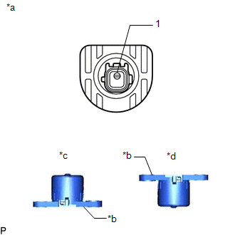
(b) Install a new clip to the engine oil level sensor as shown in the illustration. |
|
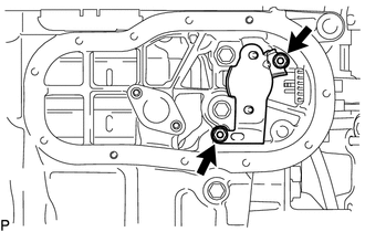
(c) Install the oil level sensor bracket with the 2 nuts.
Torque:
10 N·m {102 kgf·cm, 7 ft·lbf}
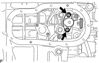
(d) Install the engine oil level sensor with the 2 nuts.
Torque:
10 N·m {102 kgf·cm, 7 ft·lbf}
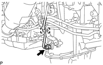
(e) Engage the clamp and disconnect the engine oil level sensor connector.
2. INSTALL OIL STRAINER SUB-ASSEMBLY
.gif)
3. INSTALL NO. 2 OIL PAN SUB-ASSEMBLY
4. ADD ENGINE OIL
5. INSPECT FOR OIL LEAK
6. INSPECT ENGINE OIL LEVEL
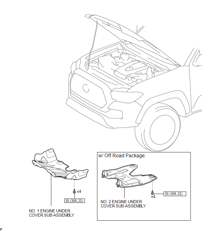
7. INSTALL NO. 1 ENGINE UNDER COVER SUB-ASSEMBLY
8. INSTALL NO. 2 ENGINE UNDER COVER SUB-ASSEMBLY (w/ Off Road Package)
Removal
REMOVAL
PROCEDURE
1. REMOVE NO. 2 ENGINE UNDER COVER SUB-ASSEMBLY (w/ Off Road Package)
2. REMOVE NO. 1 ENGINE UNDER COVER SUB-ASSEMBLY
3. DRAIN ENGINE OIL
.gif)
4. REMOVE NO. 2 OIL PAN SUB-ASSEMBLY
5. REMOVE OIL STRAINER SUB-ASSEMBLY
6. REMOVE ENGINE OIL LEVEL SENSOR
|
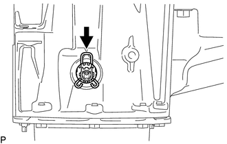
(a) Disengage the clamp and disconnect the engine oil level sensor connector. |
|
|
(b) Remove the clip from the engine oil level sensor. |
|

|
(c) Remove the 2 nuts from the engine oil level sensor. |
|
|
(d) Remove the 2 nuts and oil level sensor bracket. |
|
(e) Remove the engine oil level sensor.
 Replacement
REPLACEMENT
CAUTION / NOTICE / HINT
CAUTION:
Prolonged and repeated contact with engine oil will result in the removal
of natural oils from the skin, leading to dryness, irritation and ...
 Oil Pressure Switch
Components
COMPONENTS
ILLUSTRATION
Removal
REMOVAL
PROCEDURE
1. REMOVE ENGINE OIL PRESSURE SWITCH ASSEMBLY
(a) Disengage the clamp and disconnect the engine oil pressure switch ...
Other materials:
Diagnosis System
DIAGNOSIS SYSTEM
1. DESCRIPTION
(a) The power window control system data can be read from the Data Link Connector
3 (DLC3) of the vehicle. When the system seems to be malfunctioning, use the Techstream
to check for malfunctions and perform repairs.
2. CHECK DLC3
(a) Check the DLC3 (See page ...
Open in Stop Light Switch Circuit (C1425)
DESCRIPTION
The skid control ECU (brake actuator assembly) detects the brake operating conditions
through a signal transmitted by the stop light switch.
The skid control ECU incorporates a circuit to detect an open circuit. This DTC
is output when an open circuit is detected in the stop light ...
Parking Brake Switch Circuit
DESCRIPTION
This circuit is from the parking brake switch assembly to the navigation receiver
assembly.
WIRING DIAGRAM
PROCEDURE
1.
CHECK VEHICLE SIGNAL (OPERATION CHECK)
(a) Display the "Vehicle Signal Check Mode" screen (See page
). ...
