Toyota Tacoma (2005ŌĆō2015) Owners Manual: Luggage compartment
*: If equipped
 Instrument panel
*1: 4WD models only
*2: If equipped
*3: Vehicles with a manual transmission
*: Refer to ŌĆ£NAVIGATION SYSTEM OWNERŌĆÖS MANUALŌĆØ.
*1: If equipped
*2: 4WD models only ...
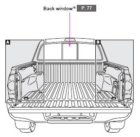
 Luggage compartment
*: If equipped ...
Other materials:
System Description
SYSTEM DESCRIPTION
GENERAL
The cruise control main switch is used to turn the dynamic radar cruise control
system on and off, as well as operate 7 functions: SET, - (COAST), TAP-DOWN, RES
(RESUME), + (ACCEL), TAP-UP and CANCEL. The SET, TAP-DOWN, and - (COAST) functions,
and the RES (RESUME) ...
ECM Communication Circuit Malfunction (C1203)
DESCRIPTION
The circuit sends TRAC, A-TRAC and VSC control information from the skid control
ECU (master cylinder solenoid) to the ECM, and engine control information from the
ECM to the skid control ECU (master cylinder solenoid) via the CAN communication
system.
DTC Code
...
On-vehicle Inspection
ON-VEHICLE INSPECTION
PROCEDURE
1. INSPECT FLUID LEVEL IN RESERVOIR
(a) Check the fluid level.
If the brake fluid level is lower than the MIN line, check for leaks and inspect
the disc brake pads. If necessary, refill the reservoir with brake fluid to the
MAX line after repair or replaceme ...
