Toyota Tacoma (2015-2018) Service Manual: Interior Light Auto Cut Circuit
DESCRIPTION
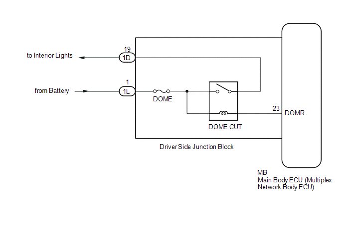
When the battery saving control operates, the main body ECU (multiplex network body ECU) controls the operation of the DOME CUT relay, that is built in to the driver side junction block, to turn off the interior lights.
WIRING DIAGRAM
CAUTION / NOTICE / HINT
NOTICE:
- Inspect the fuses for circuits related to this system before performing the following inspection procedure.
- If the main body ECU (multiplex network body ECU) is replaced, refer
to Registration (See page
.gif) ).*1
).*1
- *1: w/ Smart Key System
PROCEDURE
|
1. |
PERFORM ACTIVE TEST USING TECHSTREAM (RELAY FOR INTERIOR LIGHT AUTO CUT FUNCTION) |
(a) Connect the Techstream to the DLC3.
(b) Turn the ignition switch to ON.
(c) Turn the Techstream on.
(d) Enter the following menus: Body Electrical / Main Body / Active Test.
(e) Perform the Active Test according to the display on the Techstream.
Main Body|
Tester Display |
Test Part |
Control Range |
Diagnostic Note |
|---|---|---|---|
|
Relay for Interior Light Auto Cut Function |
DOME CUT relay |
ON/OFF |
|
OK:
DOME CUT relay operates.
| OK | .gif) |
PROCEED TO NEXT SUSPECTED AREA SHOWN IN PROBLEM SYMPTOMS TABLE |
|
.gif)
|
2. |
CHECK HARNESS AND CONNECTOR (DOME FUSE - DRIVER SIDE JUNCTION BLOCK) |
(a) Disconnect the 1L driver side junction block connector.
(b) Measure the voltage according to the value(s) in the table below.
Standard Voltage:
|
Tester Connection |
Condition |
Specified Condition |
|---|---|---|
|
1L-1 - Body ground |
Always |
11 to 14 V |
| NG | |
REPAIR OR REPLACE HARNESS OR CONNECTOR |
|
|
3. |
REPLACE DRIVER SIDE JUNCTION BLOCK |
(a) Replace the driver side junction block (See page
).
|
|
4. |
PERFORM ACTIVE TEST USING TECHSTREAM (RELAY FOR INTERIOR LIGHT AUTO CUT FUNCTION) |
(a) Connect the Techstream to the DLC3.
(b) Turn the ignition switch to ON.
(c) Turn the Techstream on.
(d) Enter the following menus: Body Electrical / Main Body / Active Test.
(e) Perform the Active Test according to the display on the Techstream.
Main Body|
Tester Display |
Test Part |
Control Range |
Diagnostic Note |
|---|---|---|---|
|
Relay for Interior Light Auto Cut Function |
DOME CUT relay |
ON/OFF |
|
OK:
DOME CUT relay operates.
| OK | |
END (DRIVER SIDE JUNCTION BLOCK WAS DEFECTIVE) |
| NG | |
REPLACE MAIN BODY ECU (MULTIPLEX NETWORK BODY ECU) |
 Hazard Warning Switch Circuit
DESCRIPTION
The combination meter assembly receives information signals from the telltale
light assembly (hazard warning signal switch).
WIRING DIAGRAM
CAUTION / NOTICE / HINT
NOTICE:
Inspect ...
 Interior Light Circuit
DESCRIPTION
The illuminated entry system controls the interior lights.
WIRING DIAGRAM
CAUTION / NOTICE / HINT
NOTICE:
Inspect the fuses for circuits related to this system before perfor ...
Other materials:
Removal
REMOVAL
CAUTION / NOTICE / HINT
NOTICE:
Release the vacuum from booster by depressing the brake pedal several times.
Then remove the brake master cylinder from brake booster.
PROCEDURE
1. PRECAUTION
NOTICE:
After turning the ignition switch off, waiting time may be required before disconnect ...
Diagnosis System
DIAGNOSIS SYSTEM
1. DESCRIPTION
(a) When troubleshooting OBD II (On-Board Diagnostics) vehicles, an OBD II scan
tool (complying with SAE J1978) must be connected to the DLC3 (Data Link Connector
3) of the vehicle. Various data in the vehicle ECM (Engine Control Module) can be
then read.
(b) ...
Parts Location
PARTS LOCATION
ILLUSTRATION
ILLUSTRATION
ILLUSTRATION
ILLUSTRATION
...
