Toyota Tacoma (2015-2018) Service Manual: Installation
INSTALLATION
PROCEDURE
1. INSTALL EXHAUST MANIFOLD SUB-ASSEMBLY LH
(a) Install a new gasket to the cylinder head LH.
NOTICE:
Be careful of the installation direction.
(b) Temporarily install the exhaust manifold sub-assembly LH with the 4 nuts.
|
(c) Tighten the 4 nuts in the sequence shown in the illustration. Torque: 21 N·m {214 kgf·cm, 15 ft·lbf} |
|

2. INSTALL NO. 2 EXHAUST MANIFOLD HEAT INSULATOR
(a) Install the No. 2 exhaust manifold heat insulator to the exhaust manifold sub-assembly LH with the 3 bolts.
Torque:
13 N·m {133 kgf·cm, 10 ft·lbf}
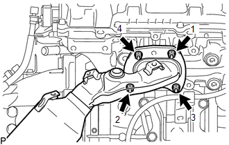
3. INSTALL NO. 2 MANIFOLD STAY
(a) Install the No. 2 manifold stay to the transmission assembly and exhaust manifold sub-assembly LH with the 3 bolts.
Torque:
40 N·m {408 kgf·cm, 30 ft·lbf}
4. INSTALL EXHAUST MANIFOLD SUB-ASSEMBLY RH
(a) Install a new gasket to the cylinder head sub-assembly.
NOTICE:
Be careful of the installation direction.
(b) Temporarily install the exhaust manifold sub-assembly RH with the 4 nuts.
|
(c) Tighten the 4 nuts in the sequence shown in the illustration. Torque: 21 N·m {214 kgf·cm, 15 ft·lbf} |
|
5. INSTALL NO. 1 EXHAUST MANIFOLD HEAT INSULATOR
(a) Install the No. 1 exhaust manifold heat insulator to the exhaust manifold sub-assembly RH with the 3 bolts.
Torque:
13 N·m {133 kgf·cm, 10 ft·lbf}
6. INSTALL MANIFOLD STAY
(a) Install the manifold stay to the transmission assembly and exhaust manifold sub-assembly RH with the 3 bolts.
Torque:
40 N·m {408 kgf·cm, 30 ft·lbf}
7. INSTALL AIR FUEL RATIO SENSOR (for Bank 1 Sensor 1)
.gif)
8. INSTALL AIR FUEL RATIO SENSOR (for Bank 2 Sensor 1)
9. INSTALL FRONT NO. 2 EXHAUST PIPE ASSEMBLY
(a) Install the 2 new gaskets to the front No. 2 exhaust pipe assembly.
(b) Connect the front No. 2 exhaust pipe assembly to the exhaust pipe support.
(c) Install the front No. 2 exhaust pipe assembly with the 2 bolts and 2 new nuts.
Torque:
for nut :
54 N·m {554 kgf·cm, 40 ft·lbf}
for bolt :
48 N·m {489 kgf·cm, 35 ft·lbf}
(d) Connect the connector.
10. INSTALL EXHAUST PIPE STOPPER BRACKET (for 4WD)
11. INSTALL CENTER NO. 2 FLOOR HEAT INSULATOR SUB-ASSEMBLY (for 4WD)
12. INSTALL FRONT EXHAUST PIPE ASSEMBLY
|
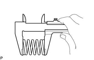
(a) Using a vernier caliper, measure the free length of the compression spring. Minimum free length: 40.5 mm (1.59 in.) If the free length is less than the minimum, replace the compression spring. |
|
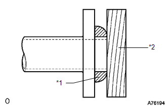
(b) Temporarily install a new exhaust pipe gasket to the front exhaust pipe assembly.
|
(c) Using a plastic hammer and wooden block, tap in a new gasket until its surface is flush with the front exhaust pipe assembly. Text in Illustration
NOTICE:
|
|
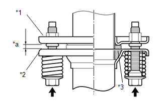
(d) Install a new gasket to the front exhaust pipe assembly.
(e) Install the front exhaust pipe assembly and 2 compression springs with the 2 new nuts.
Torque:
54 N·m {554 kgf·cm, 40 ft·lbf}
|
(f) Install the front exhaust pipe assembly with the 2 compression springs and 2 bolts. Text in Illustration
Torque: 43 N·m {438 kgf·cm, 32 ft·lbf} HINT: After the installation, check that the gaps between the flanges of the front exhaust pipe assembly and center exhaust pipe assembly are consistent front-to-rear and left-to-right. |
|
13. INSTALL FRONT FENDER SEAL LH
(a) Install the front fender seal LH with the 5 clips.
14. INSTALL FRONT FENDER SEAL RH
HINT:
Use the same procedure as for the LH side.
15. INSPECT FOR EXHAUST GAS LEAK
- Perform Inspection After Repair after repairing an exhaust gas leak.
(See page
)
 Components
COMPONENTS
ILLUSTRATION
ILLUSTRATION
...
 Removal
REMOVAL
PROCEDURE
1. REMOVE FRONT FENDER SEAL LH
(a) Remove the 5 clips and front fender seal LH.
2. REMOVE FRONT FENDER SEAL RH
HINT:
Use th ...
Other materials:
Components
COMPONENTS
ILLUSTRATION
ILLUSTRATION
ILLUSTRATION
ILLUSTRATION
...
Tire information
Typical tire symbols
1. Tire size
2. DOT and Tire Identification Number (TIN)
3. Location of treadwear indicators
4. Tire ply composition and materials
Plies are layers of rubber-coated parallel cords. Cords are the strands which
form the plies in a tire.
5. Uniform tire quality grading
F ...
If your vehicle has to be stopped in an emergency
Only in an emergency, such as if it becomes impossible to stop the vehicle
in the normal way, stop the vehicle using the following procedure:
Steadily step on the brake pedal
with both feet and firmly depress it.
Do not pump the brake pedal repeatedly as this will increase the effort required ...
