Toyota Tacoma (2015-2018) Service Manual: Inspection
INSPECTION
PROCEDURE
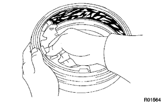
1. INSPECT BRAKE DRUM INSIDE DIAMETER
(a) Using a brake drum gauge or equivalent, measure the inside diameter of the drum.
Standard inside diameter:
254 mm (10.00 in.)
Maximum inside diameter:
256 mm (10.08 in.)
If the inside diameter is greater than the maximum, replace the brake drum.
2. INSPECT REAR DRUM BRAKE SHOE LINING THICKNESS
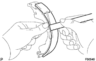
(a) Using a ruler, measure the thickness of the shoe lining.
Standard thickness:
5.0 mm (0.197 in.)
Minimum thickness:
1.0 mm (0.0394 in.)
If the lining thickness is the minimum value or less, or if there is any severe or uneven wear, replace the brake shoe.
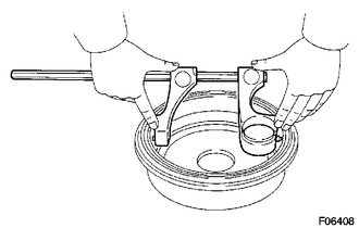
3. INSPECT BRAKE DRUM AND REAR DRUM BRAKE SHOE LINING FOR PROPER CONTACT
(a) Apply chalk to the inside surface of the drum, then grind the brake shoe lining for proper fitting.
If the contact between the drum and the shoe lining is improper, repair it using a brake shoe grinder or replace the brake shoe assembly.
4. INSPECT REAR WHEEL BRAKE CYLINDER
(a) Check the cylinder bore and piston for rust and scoring.
 Removal
REMOVAL
PROCEDURE
1. REMOVE REAR WHEEL
2. DRAIN BRAKE FLUID
HINT:
Immediately wash off any brake fluid that comes into contact with any painted
surfaces.
3. REMOVE REAR BRAKE DRUM SUB-ASSEMBLY ...
 Reassembly
REASSEMBLY
PROCEDURE
1. INSTALL REAR WHEEL CYLINDER CUP KIT
(a) Provisionally tighten the bleeder plug to the rear wheel brake cylinder,
and install the bleeder plug cap.
(b) Apply lithium soa ...
Other materials:
Customize Parameters
CUSTOMIZE PARAMETERS
1. CUSTOMIZING FUNCTION WITH TECHSTREAM
NOTICE:
When the customer requests a change in a function, first make sure that
the function can be customized.
Be sure to make a note of the current settings before customizing.
When troubleshooting a function, f ...
Fuel Sender Gauge Assembly
Components
COMPONENTS
ILLUSTRATION
Inspection
INSPECTION
PROCEDURE
1. INSPECT FUEL SENDER GAUGE ASSEMBLY
(a) Check that the float moves smoothly between F and E.
Text in Illustration
*a
Component without harness connected
(Fuel Sen ...
Front Evaporator Temperature Sensor
Inspection
INSPECTION
PROCEDURE
1. INSPECT COOLER THERMISTOR SENSOR
(a) Check the resistance.
(1) Measure the resistance and check the results in accordance with the
values in the table below.
Standard:
Tester Connection
Condition
...
