Toyota Tacoma (2015-2018) Service Manual: IG Supply Voltage Low (C120B)
DESCRIPTION
|
DTC No. |
Detection Item |
DTC Detection Condition |
Trouble Area |
|---|---|---|---|
|
C120B |
IG Supply Voltage Low |
Master cylinder pressure sensor power supply voltage decrease occurs or history of voltage decrease exists, and defective master cylinder pressure sensor output continues for 1 second or more. |
|
WIRING DIAGRAM
Refer to DTC C1417 (See page .gif) ).
).
CAUTION / NOTICE / HINT
NOTICE:
- When replacing the skid control ECU (brake actuator assembly), perform
zero point calibration and store system information (See page
).
- Inspect the fuses for circuits related to this system before performing the following procedure.
PROCEDURE
|
1. |
CHECK HARNESS AND CONNECTOR (+BS TERMINAL) |
|
(a) Make sure that there is no looseness at the locking part and the connecting part of the connector. |
|
(b) Disconnect the skid control ECU (brake actuator assembly) connector.
(c) Measure the voltage according to the value(s) in the table below.
Standard Voltage:
|
Tester Connection |
Condition |
Specified Condition |
|---|---|---|
|
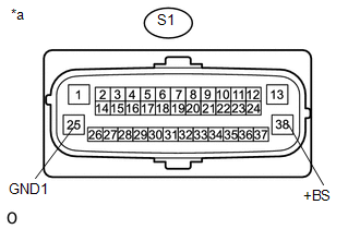
S1-38 (+BS) - Body ground |
Always |
11 to 14 V |
|
S1-38 (+BS) - S1-25 (GND1) |
Always |
11 to 14 V |
|
*a |
Front view of wire harness connector (to Skid Control ECU [Brake Actuator Assembly]) |
| NG | .gif) |
REPAIR OR REPLACE HARNESS OR CONNECTOR (+BS CIRCUIT) |
|
.gif)
|
2. |
RECONFIRM DTC |
(a) Reconnect the S1 skid control ECU (brake actuator assembly) connector.
(b) Clear the DTCs (See page
).
(c) Check if the same DTC is recorded (See page
).
|
Result |
Proceed to |
|---|---|
|
DTC C120B is not output. |
A |
|
DTC C120B is output. |
B |
| A | |
USE SIMULATION METHOD TO CHECK |
| B | |
REPLACE BRAKE ACTUATOR ASSEMBLY |
 Control Module Communication Bus OFF (U0073,U0100,U0124,U0126)
DESCRIPTION
The skid control ECU (brake actuator assembly) receives the signals from the
ECM, steering angle sensor (spiral cable with sensor sub-assembly), 4 wheel drive
control ECU*, and yaw ra ...
 Zero Point Calibration of Yaw Rate Sensor Undone (C1210,C1336)
DESCRIPTION
The skid control ECU (brake actuator assembly) receives signals from the yaw
rate and acceleration sensor (airbag sensor assembly) via the CAN communication
system.
The airbag sensor ...
Other materials:
Brake System (P157800)
DESCRIPTION
This DTC is output when the VSC system has a problem. Check the VSC system when
this DTC is output.
DTC No.
DTC Detection Condition
Trouble Area
MIL
Note
P157800
Diagnosis Condition:
Cr ...
Back-up Light Switch
Components
COMPONENTS
ILLUSTRATION
Inspection
INSPECTION
PROCEDURE
1. INSPECT BACK-UP LIGHT SWITCH ASSEMBLY
(a) Measure the resistance according to the value(s) in the table below.
Text in Illustration
*a
Pushed
...
Components
COMPONENTS
ILLUSTRATION
ILLUSTRATION
ILLUSTRATION
ILLUSTRATION
...
