Toyota Tacoma (2015-2018) Service Manual: Hydraulic Test
HYDRAULIC TEST
1. PERFORM HYDRAULIC TEST
(a) Measure the line pressure.
CAUTION:
The line pressure test should always be performed with at least 2 people. One person should observe the condition of the wheels and wheel chocks while the other is performing the test.
NOTICE:
- Perform the test while the ATF (Automatic Transmission Fluid) temperature is between 50 and 80°C (122 and 176°F).
- Be careful to prevent the hose of SST from interfering with the exhaust pipe.
- This check must be conducted after checking and adjusting the engine.
- Perform the test with the air conditioning off.
- When conducting stall test, do not continue for more than 5 seconds.
- When performing the stall speed test more than once, make sure to wait 15 seconds or more between tests.
(1) Warm up the ATF (Automatic Transmission Fluid).
(2) Turn the ignition switch off.
(3) Lift the vehicle up.
(4) Remove the test plug from the transmission case and connect SST.
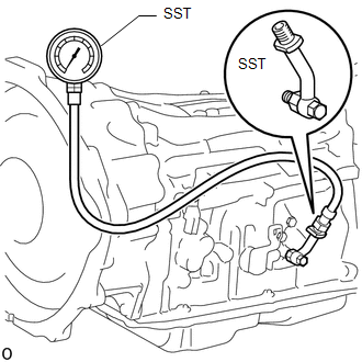
SST: 09993-19015
09993-00010
09993-00040
(5) Lower the vehicle.
(6) Fully apply the parking brake and chock the 4 wheels.
(7) Start the engine and check the idling speed.
(8) Keep your left foot pressed firmly on the brake pedal and move the shift lever to D.
(9) Fully depress the accelerator pedal with your right foot. Quickly read the highest line pressure when the engine speed reaches the stall speed.
(10) In the same manner, perform the test with the shift lever in R.
Specified Line Pressure|
Condition |
D Position |
R Position |
|---|---|---|
|
Stall speed |
1450 to 1740 kPa (14.8 to 17.7 kgf/cm2, 210 to 252 psi) |
1550 to 1840 kPa (15.8 to 18.8 kgf/cm2, 225 to 267 psi) |
|
Problem |
Possible Cause |
|---|---|
|
Measured values are higher than the specified value in all positions |
|
|
Measured values are lower than the specified value in all positions |
|
|
Pressure is low in D position only |
|
|
Pressure is low in R position only |
|
 System Diagram
SYSTEM DIAGRAM
The configuration of the electronic control system in the AC60E automatic transmission
is as shown in the following chart.
...
 Mechanical System Tests
MECHANICAL SYSTEM TESTS
1. STALL SPEED TEST
HINT:
This test is to check the overall performance of the engine and transmission.
CAUTION:
This test should be done on a paved surface (a sur ...
Other materials:
FCM Destination Information Unmatched (C1AA1)
DESCRIPTION
When the forward recognition camera is replaced with a new one, the new forward
recognition camera attempts to store country specification information received
from the main body ECU (multiplex network body ECU) and ECM. If the country specification
information stored in the forwa ...
On-vehicle Inspection
ON-VEHICLE INSPECTION
PROCEDURE
1. INSPECT PARK/NEUTRAL POSITION SWITCH
(a) Apply the parking brake.
(b) Turn the ignition switch to ON.
(c) Depress the brake pedal and move the shift lever to any position other than
P.
(d) Depress the brake pedal and check that the engine starts when the sh ...
Freeze Frame Data
FREEZE FRAME DATA
1. FREEZE FRAME DATA
(a) Using the Techstream, check the vehicle condition (ECU, sensor) when the
brake system operates or a DTC is output.
2. CHECK FREEZE FRAME DATA WHEN BRAKE SYSTEM OPERATES
(a) Freeze frame data is stored when the brake system operates. The freeze frame
...
