Toyota Tacoma (2015-2018) Service Manual: Disassembly
DISASSEMBLY
PROCEDURE
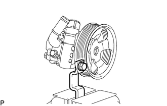
1. FIX VANE PUMP ASSEMBLY
|
(a) Using SST, fix the vane pump assembly in a vise. SST: 09630-00014 09631-00132 NOTICE: When using a vise, do not overtighten it. |
|
2. REMOVE POWER STEERING SUCTION PORT UNION
|
(a) Remove the bolt and suction port union. |
|
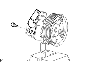
(b) Remove the O-ring from the suction port union.
3. REMOVE FLOW CONTROL VALVE ASSEMBLY
|
(a) Remove the pressure port union. |
|
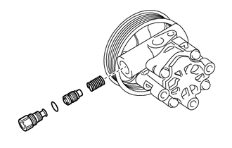
(b) Remove the O-ring from the pressure port union.
(c) Remove the flow control valve assembly and compression spring.
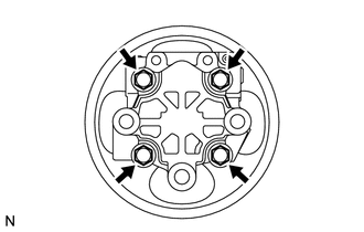
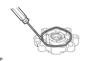
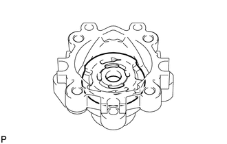
4. REMOVE REAR VANE PUMP HOUSING
|
(a) Remove the 4 bolts and rear vane pump housing from the front vane pump housing. |
|
|
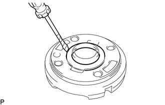
(b) Using a screwdriver, remove the O-ring from the rear vane pump housing. |
|
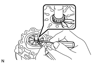
5. REMOVE PULLEY SHAFT SUB-ASSEMBLY
(a) Using a screwdriver, remove the snap ring from the pulley shaft sub-assembly.
|
(b) Remove the pulley shaft. NOTICE: Be careful not to drop or damage the pulley shaft. If damaged, replace it with a new one. |
|
6. REMOVE VANE PUMP ROTOR
|
(a) Remove the 10 vane pump plates. NOTICE: Take care not to drop the vane pump plates. |
|
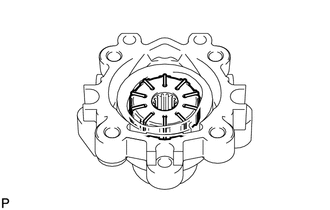
(b) Remove the vane pump rotor from the front vane pump housing.
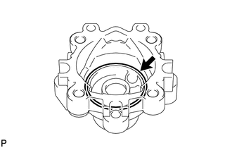
7. REMOVE VANE PUMP CAM RING
|
(a) Remove the vane pump cam ring from the front vane pump housing. |
|
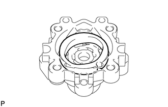
8. REMOVE FRONT VANE PUMP SIDE PLATE
|
(a) Remove the front vane pump side plate from the front vane pump housing. |
|
|
(b) Using a screwdriver, remove the O-ring from the front vane pump side plate. |
|
|
(c) Remove the O-ring from the front vane pump housing. |
|
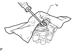
9. REMOVE VANE PUMP HOUSING OIL SEAL
|
(a) Using screwdriver, remove the vane pump housing oil seal. Text in Illustration
NOTICE: Be careful not to damage the front vane pump housing. |
|
 Components
COMPONENTS
ILLUSTRATION
ILLUSTRATION
...
 Removal
REMOVAL
PROCEDURE
1. REMOVE NO. 2 ENGINE UNDER COVER SUB-ASSEMBLY (w/ Off Road Package)
2. REMOVE NO. 1 ENGINE UNDER COVER SUB-ASSEMBLY
3. REMOVE FAN AND GENERATOR V BELT
4. DRAIN POWER STEERI ...
Other materials:
Removal
REMOVAL
PROCEDURE
1. REMOVE FUEL TANK ASSEMBLY
Click here
2. DISCONNECT CHARCOAL CANISTER FUEL HOSE
(a) Loosen the hose clip and disconnect the charcoal canister fuel hose.
3. DISCONNECT FUEL TANK VENT HOSE
(a) Push the fuel tank vent hos ...
Utility
UTILITY
NOTICE:
If the forward recognition camera has been replaced with a new one or
the windshield glass has been removed and installed, it is necessary to
perform Forward Recognition Camera Axis Adjustment. If the system is turned
on without performing Forward Recognition Ca ...
Diagnostic Trouble Code Chart
DIAGNOSTIC TROUBLE CODE CHART
TOUCH SELECT 2-4 AND HIGH-LOW SYSTEM
DTC Code
Detection Item
See page
P163B
4WD ECU Malfunction
P17A0
Automatic Disconnecting Differential Motor Control Circuit Open
...
