Toyota Tacoma (2015-2018) Service Manual: Crawl Switch
Components
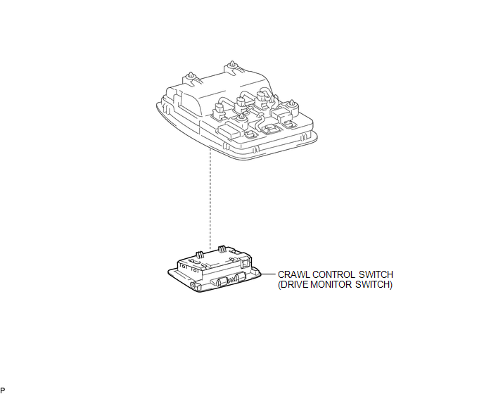
COMPONENTS
ILLUSTRATION
Inspection
INSPECTION
PROCEDURE
1. INSPECT CRAWL CONTROL SWITCH (DRIVE MONITOR SWITCH)
(a) Check the resistance.
(1) Measure the resistance according to the value(s) in the table below.
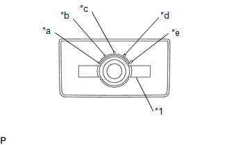 Text in Illustration
|
*1 |
Crawl Control Switch |
|
*a |
Low |
|
*b |
Between Low and Medium |
|
*c |
Medium |
|
*d |
Between Medium and High |
|
*e |
High |
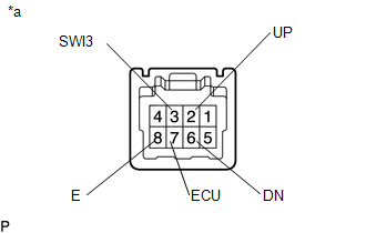
Standard Resistance:
|
Tester Connection |
Switch Condition |
Specified Condition |
|---|---|---|
|
7 (ECU) - 8 (E) |
Low |
Below 1 Ω |
|
2 (UP) - 8 (E) |
||
|
6 (DN) - 8 (E) |
10 kΩ or higher |
|
|
7 (ECU) - 8 (E) |
Between Low and Medium |
Below 1 Ω |
|
2 (UP) - 8 (E) |
||
|
6 (DN) - 8 (E) |
10 kΩ or higher |
|
|
7 (ECU) - 8 (E) |
Medium |
Below 1 Ω |
|
2 (UP) - 8 (E) |
||
|
6 (DN) - 8 (E) |
10 kΩ or higher |
|
|
7 (ECU) - 8 (E) |
Between Medium and High |
Below 1 Ω |
|
2 (UP) - 8 (E) |
||
|
6 (DN) - 8 (E) |
10 kΩ or higher |
|
|
7 (ECU) - 8 (E) |
High |
Below 1 Ω |
|
2 (UP) - 8 (E) |
||
|
6 (DN) - 8 (E) |
10 kΩ or higher |
|
|
3 (SWl3) - 8 (E) |
ON/OFF: Pressed |
Below 1 Ω |
|
ON/OFF: Not pressed |
10 kΩ or higher |
|
*a |
Component without harness connected (Crawl Control Switch (Drive Monitor Switch)) |
If the result is not as specified, replace the crawl control switch (drive monitor switch).
Removal
REMOVAL
PROCEDURE
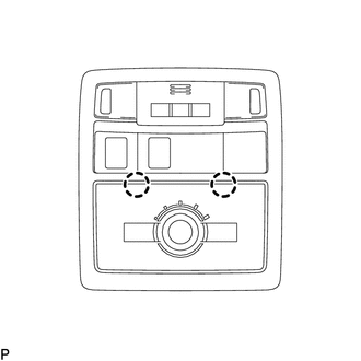
1. REMOVE CRAWL CONTROL SWITCH (DRIVE MONITOR SWITCH)
|
(a) Disengage the 2 claws to remove the crawl control switch (drive monitor switch). |
|
Installation
INSTALLATION
PROCEDURE
1. INSTALL CRAWL CONTROL SWITCH (DRIVE MONITOR SWITCH)
(a) Engage the 2 claws to install the crawl control switch (drive monitor switch).
 Removal
REMOVAL
PROCEDURE
1. PRECAUTION
NOTICE:
After turning the ignition switch off, waiting time may be required before disconnecting
the cable from the negative (-) battery terminal.
Therefore, mak ...
 Front Speed Sensor
Removal
REMOVAL
PROCEDURE
1. PRECAUTION
NOTICE:
After turning the ignition switch off, waiting time may be required before disconnecting
the cable from the negative (-) battery terminal.
The ...
Other materials:
Operation Check
OPERATION CHECK
1. CHECK PANEL & STEERING SWITCH
HINT:
The radio and display receiver assembly panel switches and steering
switches are checked in the following procedure.
Illustrations may differ from the actual vehicle screen depending on
the device settings and options. ...
Problem Symptoms Table
PROBLEM SYMPTOMS TABLE
HINT:
If a problem occurs in certain locations or at certain times of day,
check for the possibility of wave interference.
When the electrical key transmitter sub-assembly is brought near the
electrical key and TPMS receiver assembly (RF band), front outs ...
Differential System(w/o Differential Lock)
Precaution
PRECAUTION
1. Before disassembly, clean the outside of the front and rear differential assembly
and remove any sand and mud to prevent it from entering the assembly during disassembly
and installation.
2. When removing connected parts made of a light alloy, such as front and rear ...
