Toyota Tacoma (2005–2015) Owners Manual: Correct driving posture
Drive in a good posture as follows:
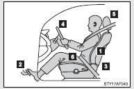
 Sit upright and well back in the
seat.
Sit upright and well back in the
seat.
 Adjust the position of the seat
forward or backward to ensure the pedals can be reached and easily depressed to
the extent required.
Adjust the position of the seat
forward or backward to ensure the pedals can be reached and easily depressed to
the extent required.
 Adjust the seatback so that the
controls are easily operable.
Adjust the seatback so that the
controls are easily operable.
 Adjust the tilt and telescopic positions
of the steering wheel downward so the airbag is facing your chest.
Adjust the tilt and telescopic positions
of the steering wheel downward so the airbag is facing your chest.
 Lock the head restraint in place
with the center of the head restraint closest to the top of your ears.
Lock the head restraint in place
with the center of the head restraint closest to the top of your ears.
 Wear the seat belt correctly.
CAUTION
■While driving
●Do not adjust the position of the driver’s seat while driving.
Doing so could cause the driver to lose control of the vehicle.
●Do not place a cushion between the driver or passenger and the seatback.
A cushion may prevent correct posture from being achieved, and reduce the effectiveness of the seat belt and head restraint, increasing the risk of death or serious injury to the driver or passenger.
●Do not place anything under the front seats.
Objects placed under the front seats may become jammed in the seat tracks and stop the seat from locking in place. This may lead to an accident.
The adjustment mechanism may also be damaged.
■Adjusting the seat position
●Take care when adjusting the seat position to ensure that other passengers are not injured by the moving seat.
●Do not put your hands under the seat or near the moving parts to avoid injury.
Fingers or hands may become jammed in the seat mechanism.

 SRS airbags
The SRS airbags inflate when the vehicle is subjected to certain types of severe
impacts that may cause significant injury to the occupants. They work together with
the seat belts to help reduce t ...
Other materials:
Diagnostic Trouble Code Chart
DIAGNOSTIC TROUBLE CODE CHART
If a DTC is displayed during the DTC check, check the parts listed in
the table below and proceed to the "See page" given.
*1: "Comes on" means the Malfunction Indicator Lamp (MIL) illuminates.
*2: "DTC stored" means ...
Customize Parameters
CUSTOMIZE PARAMETERS
PROCEDURE
1. CUSTOMIZE POWER WINDOW CONTROL SYSTEM
HINT:
The following items can be customized.
NOTICE:
When the customer requests a change in a function, first make sure that
the function can be customized.
Record the current settings before customizing.
...
Washer Motor
Components
COMPONENTS
ILLUSTRATION
On-vehicle Inspection
ON-VEHICLE INSPECTION
PROCEDURE
1. INSPECT WINDSHIELD WASHER MOTOR AND PUMP ASSEMBLY
HINT:
This check should be performed with the windshield washer motor and pump assembly
installed to the windshield washer jar assembly.
...
