Toyota Tacoma (2015-2018) Service Manual: Components
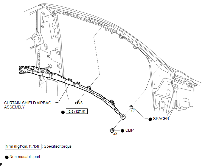
COMPONENTS
ILLUSTRATION

 On-vehicle Inspection
ON-VEHICLE INSPECTION
PROCEDURE
1. INSPECT CURTAIN SHIELD AIRBAG ASSEMBLY (for Vehicle not Involved in Collision)
(a) Perform a Diagnostic System Check (See page
).
(b) With the curta ...
Other materials:
Freeze Frame Data
FREEZE FRAME DATA
CHECK FREEZE FRAME DATA
HINT:
The ECU records vehicle and driving condition information as freeze frame data
the moment a DTC is stored.
(a) Connect the Techstream to the DLC3.
(b) Turn the ignition switch to ON.
(c) Turn the Techstream on.
(d) Enter the following menus: P ...
Precaution
PRECAUTION
1. EXPRESSIONS OF IGNITION SWITCH
HINT:
The type of ignition switch used on this model differs according to the specifications
of the vehicle. The expressions listed in the table below are used in this section.
Expression
Ignition Switch
(Position)
...
Disassembly
DISASSEMBLY
CAUTION / NOTICE / HINT
HINT:
Use the same procedure for the RH side and LH side.
The following procedure is for the LH side.
When removing the No. 2 front wheel opening extension pad or No. 1 front
wheel opening extension pad or front wheel opening extension pad, ...
