TERMINALS OF ECU
1. TERMINALS OF ECU
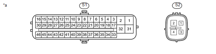 Text in Illustration
|
*a |
Component without harness connected (Skid Control ECU (Master Cylinder Solenoid)) |
- |
- |
|
Terminal No. (Symbol) |
Terminal Description |
|---|---|
|
S1-1 (GND1) |
Ground |
|
S1-2 (+BM1) |
Power supply for motor |
|
S1-3 (FR+) |
Front wheel speed sensor RH power supply output |
|
S1-4 (FL-) |
Front wheel speed LH signal input |
|
S1-5 (RR+) |
Rear wheel speed sensor RH power supply output |
|
S1-6 (RL-) |
Rear wheel speed LH signal input |
|
S1-7 (STP) |
Stop light switch input |
|
S1-9 (CSW) |
VSC OFF switch input |
|
S1-11 (CANH) |
CAN communication line H |
|
S1-12 (SP1) |
Speed signal output for speedometer |
|
S1-13 (TRM3) |
A-TRAC switch input*1 CRAWL speed selector switch*2 |
|
S1-16 (STPO) |
Stop light operated relay output |
|
S1-17 (FR-) |
Front wheel speed sensor RH input |
|
S1-18 (FL+) |
Front wheel speed sensor LH power supply output |
|
S1-19 (RR-) |
Rear wheel speed sensor RH input |
|
S1-20 (RL+) |
Rear wheel speed sensor LH power supply output |
|
S1-21 (TRM2) |
CRAWL speed selector switch*2 |
|
S1-25 (CANL) |
CAN communication line L |
|
S1-27 (EXI) |
L4 detection switch input |
|
S1-28 (PKB) |
MTS SET switch input |
|
S1-29 (EXI4) |
4WD detection switch input |
|
S1-31 (+BS) |
Power supply for solenoid |
|
S1-32 (GND2) |
Ground |
|
S1-41 (LBL) |
Brake fluid level warning switch input |
|
S1-43 (TRS) |
CRAWL ON/OFF switch*2 |
|
S1-44 (TRM1) |
CRAWL speed selector switch*2 |
|
S1-45 (STP2) |
Stop light switch input |
|
S1-46 (IG1) |
IG1 power supply |
|
S2-1 (IG2) |
IG2 power supply |
|
S2-2 (+BM2) |
Power supply for motor |
|
S2-4 (GND3) |
Ground |
- *1: for Manual Transmission
- *2: for Automatic Transmission
2. TERMINAL INSPECTION
Disconnect the connector and measure the voltage or resistance on the wire harness side.
HINT:
Voltage cannot be measured with the connector connected to the skid control ECU (master cylinder solenoid) as the connector is water resistant.
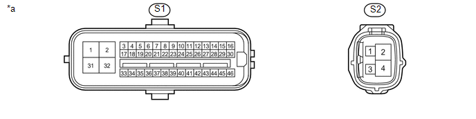 Text in Illustration
|
*a |
Front view of wire harness connector (Skid Control ECU (Master Cylinder Solenoid)) |
- |
- |
|
Terminal No. (Symbol) |
Wiring Color |
Terminal Description |
Condition |
Specified Condition |
|---|---|---|---|---|
|
S1-1 (GND1) - Body ground |
W-B - Body ground |
Ground |
Always |
Below 1 Ω |
|
S1-2 (+BM1) - Body ground |
B - Body ground |
Power supply for motor from battery |
Always |
11 to 14 V |
|
S1-7 (STP) - Body ground |
SB - Body ground |
Stop light switch input |
Stop light switch off (Brake pedal released) |
Below 1.5 V |
|
Stop light switch on (Brake pedal depressed) |
8 to 14 V |
|||
|
S1-9 (CSW) - Body ground |
GR - Body ground |
VSC OFF switch input |
VSC OFF switch off |
10 kΩ or higher |
|
VSC OFF switch on and hold |
Below 1 Ω |
|||
|
S1-16 (STPO) - Body ground |
B - Body ground |
Stop light operated relay output |
Ignition switch off |
Below 1 V |
|
Ignition switch ON |
11 to 14 V |
|||
|
S1-31 (+BS) - Body ground |
R - Body ground |
Power supply for solenoid from battery |
Always |
11 to 14 V |
|
S1-32 (GND2) - Body ground |
W-B - Body ground |
Ground |
Always |
Below 1 Ω |
|
S1-41 (LBL) - Body ground |
V - Body ground |
Brake fluid level warning switch input |
Brake fluid level min. -5 mm |
Below 1 Ω |
|
Brake fluid level max. |
1.9 to 2.1 kΩ |
|||
|
S1-45 (STP2) - Body ground |
L - Body ground |
Stop light switch input |
Stop light switch off (Brake pedal released) |
Below 1.5 V |
|
Stop light switch on (Brake pedal depressed) |
8 to 14 V |
|||
|
S1-46 (IG1) - Body ground |
G - Body ground |
IG1 power supply |
Ignition switch off |
Below 1 V |
|
Ignition switch ON |
11 to 14 V |
|||
|
S2-1 (IG2) - Body ground |
BE - Body ground |
IG2 power supply |
Ignition switch off |
Below 1 V |
|
Ignition switch ON |
11 to 14 V |
|||
|
S2-2 (+BM2) - Body ground |
B - Body ground |
Power supply for motor from battery |
Always |
11 to 14 V |
|
S2-4 (GND3) - Body ground |
W-B - Body ground |
Ground |
Always |
Below 1 Ω |