TERMINALS OF ECU
1. AIR CONDITIONING AMPLIFIER ASSEMBLY
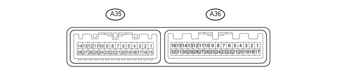
HINT:
Check from the rear of the connector while it is connected to the air conditioning amplifier assembly.
|
Terminal No. (Symbol) |
Wiring Color |
Terminal Description |
Condition |
Specified Condition |
|---|---|---|---|---|
|
A35-1 (TAM) - A36-28 (SG-8) |
W - LG |
Ambient temperature sensor signal |
|
1.35 to 1.75 V |
|
0.9 to 1.2 V |
|||
|
A35-2 (PRE) - A36-10 (GND) |
V - W-B |
Air conditioner pressure sensor signal |
|
4.71 V or higher |
|
Below 0.74 V |
|||
|
0.74 to 4.71 V |
|||
|
A35-3 (TPO) - A35-19 (SG-6) |
B - L |
Mode damper position sensor signal |
|
4.43 to 4.53 V |
|
0.47 to 0.57 V |
|||
|
A35-4 (TPR) - A35-18 (SG-5) |
G - GR |
Air mix damper position sensor (for front passenger side) signal |
|
4.45 to 4.55 V |
|
0.45 to 0.55 V |
|||
|
A35-5 (TPL) - A35-17 (SG-4) |
V - R |
Air mix damper position sensor (for driver side) signal |
|
4.45 to 4.55 V |
|
0.45 to 0.55 V |
|||
|
A35-6 (TPI) - A35-16 (SG-3) |
LG -V |
Air inlet damper position sensor signal |
|
1.63 to 1.73 V |
|
3.27 to 3.37 V |
|||
|
A35-7 (LOCK) - A36-10 (GND) |
G - W-B |
A/C lock sensor signal |
|
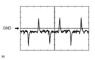
Pulse generation (See waveform 1) |
|
A35-10 (MGC) - A36-10 (GND) |
G - W-B |
Magnetic clutch operation signal |
|
11 to 14 V |
|
Below 1 V |
|||
|
A35-11 (AMDH) - A36-10 (GND) |
BE - W-B |
Air mix damper servo motor (for driver side) operating signal |
|
11 to 14 V (Servo motor operating) |
|
A35-12 (AMDC) - A36-10 (GND) |
SB - W-B |
Air mix damper servo motor (for driver side) operating signal |
|
11 to 14 V (Servo motor operating) |
|
A35-13 (AMPH) - A36-10 (GND) |
Y - W-B |
Air mix damper servo motor (for front passenger side) operating signal |
|
11 to 14 V (Servo motor (Servo motor operating) |
|
A35-14 (AMPC) - A36-10 (GND) |
W - W-B |
Air mix damper servo motor (for front passenger side) operating signal |
|
11 to 14 V (Servo motor operating) |
|
A35-16 (SG-3) - Body ground |
V - Body ground |
Ground for air inlet damper position sensor |
Always |
Below 1 Ω |
|
A35-17 (SG-4) - Body ground |
R - Body ground |
Ground for air mix damper position sensor (for driver side) |
Always |
Below 1 Ω |
|
A35-18 (SG-5) - Body ground |
GR - Body ground |
Ground for air mix damper position sensor (for front passenger side) |
Always |
Below 1 Ω |
|
A35-19 (SG-6) - Body ground |
L - Body ground |
Ground for mode damper position sensor |
Always |
Below 1 Ω |
|
A35-22 (AC1) - A36-10 (GND) |
BE - W-B |
Compressor operation signal |
|
11 to 14 V |
|
Below 1 V |
|||
|
A35-25 (AIF) - A36-10 (GND) |
P - W-B |
Air inlet damper servo motor operating signal |
|
11 to 14 V (Servo motor operating) |
|
A35-26 (AIR) - A36-10 (GND) |
B - W-B |
Air inlet damper servo motor operating signal |
|
11 to 14 V (Servo motor operating) |
|
A35-27 (AOF) - A36-10 (GND) |
LG - W-B |
Mode damper servo motor operating signal |
|
11 to 14 V (Servo motor operating) |
|
A35-28 (AOD) - A36-10 (GND) |
R - W-B |
Mode damper servo motor operating signal |
|
11 to 14 V (Servo motor operating) |
|
A35-30 (S5-5) - A36-10 (GND) |
G - W-B |
Power supply for mode damper position sensor |
Ignition switch off |
Below 1 V |
|
Ignition switch ON |
4.75 to 5.25 V |
|||
|
A36-1 (IG+) - A36-10 (GND) |
GR - W-B |
Power source (IG) |
Ignition switch ON |
11 to 14 V |
|
Ignition switch off |
Below 1 V |
|||
|
A36-4 (ACT) - A36-10 (GND) |
R - W-B |
Compressor operation signal |
|
Below 1 V |
|
4.75 to 5.25 V |
|||
|
A36-7 (HRLY) - A36-10 (GND) |
Y - W-B |
HTR relay operation signal |
|
11 to 14 V |
|
Below 1 V |
|||
|
A36-8 (CANH) |
L |
CAN communication system |
- |
- |
|
A36-9 (CANL) |
W |
CAN communication system |
- |
- |
|
A36-10 (GND) - Body ground |
W-B - Body ground |
Ground for main power supply |
Always |
Below 1 Ω |
|
A36-11 (LIN1) - A36-10 (GND) |
SB - W-B |
LIN communication signal |
Ignition switch ON |
Pulse generation |
|
A36-12 (S5-1) - A36-10 (GND) |
SB - W-B |
Power supply for air conditioner pressure sensor |
Ignition switch off |
Below 1 V |
|
Ignition switch ON |
4.5 to 5.5 V |
|||
|
A36-13 (S5-2) - A36-10 (GND) |
Y - W-B |
Power supply for air inlet damper position sensor |
Ignition switch off |
Below 1 V |
|
Ignition switch ON |
4.75 to 5.25 V |
|||
|
A36-14 (S5-3) - A36-10 (GND) |
Y - W-B |
Power supply for air mix damper position sensor (for driver side) |
Ignition switch off |
Below 1 V |
|
Ignition switch ON |
4.75 to 5.25 V |
|||
|
A36-15 (TE) - A36-27 (SG-7) |
B - GR |
Evaporator temperature sensor signal |
|
1.7 to 2.1 V |
|
0.9 to 1.3 V |
|||
|
A36-16 (TR) - A36-26 (SG-1) |
R - BR |
Room temperature sensor signal |
|
1.8 to 2.2 V |
|
1.2 to 1.6 V |
|||
|
A36-17 (B) - A36-10 (GND) |
LG - W-B |
Power source (Back-up) |
Always |
11 to 14 V |
|
A36-19 (PTC1) - A36-10 (GND)*1 |
V - W-B |
Quick heater operation signal |
|
11 to 14 V |
|
Below 1 V |
|||
|
A36-20 (PTC2) - A36-10 (GND)*1 |
W - W-B |
Quick heater operation signal |
|
11 to 14 V |
|
Below 1 V |
|||
|
A36-21 (PTC3) - A36-10 (GND)*1 |
P - W-B |
Quick heater operation signal |
|
11 to 14 V |
|
Below 1 V |
|||
|
A36-23 (BLW) - A36-10 (GND) |
BE - W-B |
Blower motor speed control signal |
|
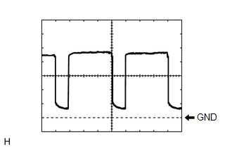
Pulse generation (See waveform 2) |
|
A36-26 (SG-1) - Body ground |
BR - Body ground |
Ground for room temperature sensor |
Always |
Below 1 Ω |
|
A36-27 (SG-7) - Body ground |
GR - Body ground |
Ground for evaporator temperature sensor |
Always |
Below 1 Ω |
|
A36-28 (SG-8) - Body ground |
LG - Body ground |
Ground for air conditioner pressure sensor, ambient temperature sensor, A/C lock sensor |
Always |
Below 1 Ω |
|
A36-29 (S5-4) - A36-10 (GND) |
R - W-B |
Power supply for air mix damper position sensor (for front passenger side) |
Ignition switch off |
Below 1 V |
|
Ignition switch ON |
4.75 to 5.25 V |
- *1: w/ PTC Heater
(a) Waveform 1:
|
Item |
Content |
|---|---|
|
Terminal No. |
A35-7 (LOCK) - A36-10 (GND) |
|
Tool Setting |
200 mV/DIV., 10 ms./DIV. |
|
Vehicle Condition |
|
(b) Waveform 2:
|
Item |
Content |
|---|---|
|
Terminal No. |
A36-23 (BLW) - A36-10 (GND) |
|
Tool Setting |
1 V/DIV., 500 μs./DIV. |
|
Vehicle Condition |
|
2. AIR CONDITIONING CONTROL ASSEMBLY

HINT:
Check from the rear of the connector while it is connected to the air conditioning control assembly.
|
Terminal No. (Symbol) |
Wiring Color |
Terminal Description |
Condition |
Specified Condition |
|---|---|---|---|---|
|
A33-8 (IG+) - A33-1 (GND) |
LG - W-B |
Power source (IG) |
Ignition switch off |
Below 1 V |
|
Ignition switch ON |
11 to 14 V |
|||
|
A33-1 (GND) - Body ground |
W-B - Body ground |
Ground for air conditioning control assembly |
Always |
Below 1 Ω |
|
A33-2 (STX) - A33-1 (GND) |
SB - W-B |
LIN communication signal |
Ignition switch ON |
Pulse generation |
3. ECM (See page .gif) )
)