DESCRIPTION
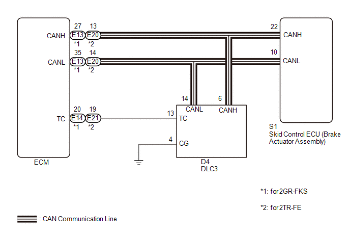
Connecting terminals TC and CG of the DLC3 causes the ECU to display the DTC by blinking the ABS warning light and slip indicator light.
WIRING DIAGRAM
CAUTION / NOTICE / HINT
NOTICE:
When replacing the skid control ECU (brake actuator assembly), perform zero point
calibration and store system information (See page
.gif) ).
).
PROCEDURE
|
1. |
CHECK CAN COMMUNICATION SYSTEM |
(a) Check if CAN communication system DTCs are output (See page
).
|
Result |
Proceed to |
|---|---|
|
DTC is not output |
A |
|
DTC is output |
B |
| B | .gif) |
CHECK CAN COMMUNICATION SYSTEM |
|
.gif)
|
2. |
INSPECT DLC3 |
|
(a) Turn the ignition switch to ON. |
|
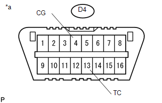
(b) Measure the voltage according to the value(s) in the table below.
Standard Voltage:
|
Tester Connection |
Switch Condition |
Specified Condition |
|---|---|---|
|
D4-13 (TC) - D4-4 (CG) |
Ignition switch ON |
11 to 14 V |
|
*a |
Front view of DLC3 |
| NG | |
GO TO STEP 4 |
|
|
3. |
REPLACE ECM |
|
(a) Turn the ignition switch off. |
|
(b) Replace the ECM.
- for 2GR-FKS: (See page
)
- for 2TR-FE: (See page
)
(c) Using SST, connect terminals 13 (TC) and 4 (CG) of the DLC3.
SST: 09843-18040
(d) Check that the ABS warning and slip indicator lights are blinking.
OK:
The ABS warning and slip indicator lights are blinking.
Text in Illustration|
*a |
Front view of DLC3 |
| OK | |
END |
| NG | |
REPLACE BRAKE ACTUATOR ASSEMBLY |
|
4. |
CHECK HARNESS AND CONNECTOR (TC of DLC3 - ECM) |
(a) Turn the ignition switch off.
(b) Disconnect the E13*1, E21*2 ECM connector.
- *1: for 2GR-FKS
- *2: for 2TR-FE
(c) Measure the resistance according to the value(s) in the table below.
Standard Resistance:
for 2GR-FKS:|
Tester Connection |
Condition |
Specified Condition |
|---|---|---|
|
D4-13 (TC) - E14-20 (TC) |
Always |
Below 1 Ω |
|
D4-13 (TC) or E14-20 (TC) - Body ground |
Always |
10 kΩ or higher |
|
Tester Connection |
Condition |
Specified Condition |
|---|---|---|
|
D4-13 (TC) - E21-19 (TC) |
Always |
Below 1 Ω |
|
D4-13 (TC) or E21-19 (TC) - Body ground |
Always |
10 kΩ or higher |
| NG | |
REPAIR OR REPLACE HARNESS OR CONNECTOR |
|
|
5. |
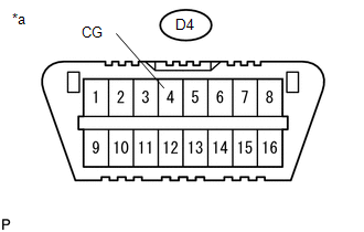
CHECK HARNESS AND CONNECTOR (CG of DLC3 - BODY GROUND) |
|
(a) Measure the resistance according to the value(s) in the table below. Standard Resistance:
|
|
| NG | |
REPAIR OR REPLACE HARNESS OR CONNECTOR |
|
|
6. |
REPLACE ECM |
|
(a) Replace the ECM.
|
|
(b) Using SST, connect terminals 13 (TC) and 4 (CG) of the DLC3.
SST: 09843-18040
(c) Check that the ABS warning and slip indicator lights are blinking.
OK:
The ABS warning and slip indicator lights are blinking.
Text in Illustration|
*a |
Front view of DLC3 |
| OK | |
END |
| NG | |
REPLACE BRAKE ACTUATOR ASSEMBLY |