Components
COMPONENTS
ILLUSTRATION
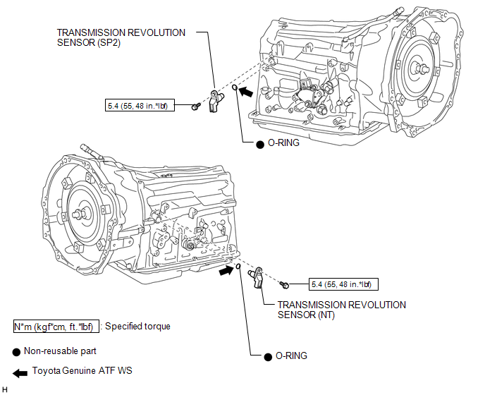
Removal
REMOVAL
PROCEDURE
1. REMOVE TRANSMISSION REVOLUTION SENSOR (NT)
|
(a) Disconnect the transmission revolution sensor (NT) connector. |
|
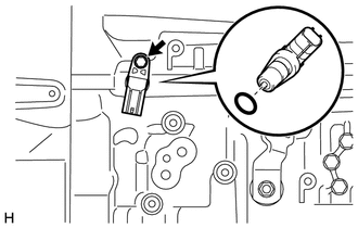
(b) Remove the bolt and transmission revolution sensor (NT).
(c) Remove the O-ring from the transmission revolution sensor (NT).
2. REMOVE TRANSMISSION REVOLUTION SENSOR (SP2)
|
(a) Disconnect the transmission revolution sensor (SP2) connector. |
|
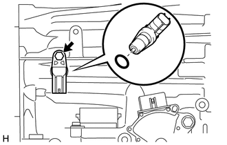
(b) Remove the bolt and transmission revolution sensor (SP2).
(c) Remove the O-ring from the transmission revolution sensor (SP2).
Inspection
INSPECTION
PROCEDURE
1. INSPECT TRANSMISSION REVOLUTION SENSOR (NT)
(a) Connect the battery to the transmission revolution sensor (NT) as shown in the illustration.
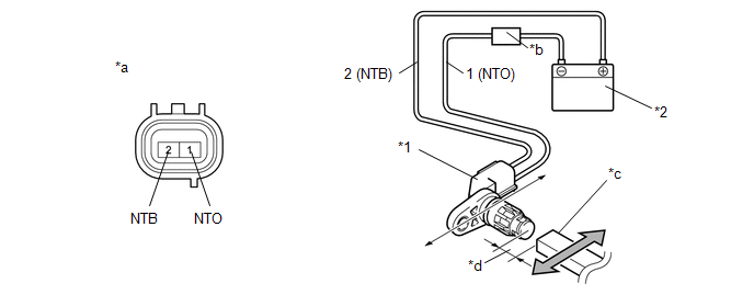 Text in Illustration
|
*1 |
Transmission Revolution Sensor (NT) |
*2 |
Battery |
|
*a |
Component without harness connected (Transmission Revolution Sensor (NT)) |
*b |
Ammeter |
|
*c |
Magnet |
*d |
5 mm (0.197 in.) or less |
(b) Wave a magnetic object left and right in front of the transmission revolution sensor (NT) tip (5 mm (0.197 in.) or less) to change the high/low signals while measuring the current.
NOTICE:
Make sure to wave the magnetic object during the inspection. The current will not change without waving the magnetic object as indicated by the arrow in the illustration.
(c) Measure the current according to the value(s) in the table below.
Standard Current:
|
Tester Connection |
Condition |
Specified Condition |
|---|---|---|
|
1 (NTO) - 2 (NTB) |
Low signal |
4 to 8 mA |
|
High signal |
12 to 16 mA |
If the result is not as specified, replace the transmission revolution sensor (NT).
2. INSPECT TRANSMISSION REVOLUTION SENSOR (SP2)
(a) Connect the battery to the transmission revolution sensor (SP2) as shown in the illustration.
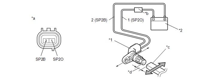 Text in Illustration
|
*1 |
Transmission Revolution Sensor (SP2) |
*2 |
Battery |
|
*a |
Component without harness connected (Transmission Revolution Sensor (SP2)) |
*b |
Ammeter |
|
*c |
Magnet |
*d |
5 mm (0.197 in.) or less |
(b) Wave a magnetic object left and right in front of the transmission revolution sensor (SP2) tip (5 mm (0.197 in.) or less) to change the high/low signals while measuring the current.
NOTICE:
Make sure to wave the magnetic object during the inspection. The current will not change without waving the magnetic object as indicated by the arrow in the illustration.
(c) Measure the current according to the value(s) in the table below.
Standard Current:
|
Tester Connection |
Condition |
Specified Condition |
|---|---|---|
|
1 (SP2O) - 2 (SP2B) |
Low signal |
4 to 8 mA |
|
High signal |
12 to 16 mA |
If the result is not as specified, replace the transmission revolution sensor (SP2).
Installation
INSTALLATION
PROCEDURE
1. INSTALL TRANSMISSION REVOLUTION SENSOR (SP2)
(a) Coat a new O-ring with ATF and install it to the transmission revolution sensor (SP2).
(b) Install the transmission revolution sensor (SP2) with the bolt.
Torque:
5.4 N·m {55 kgf·cm, 48 in·lbf}
(c) Connect the transmission revolution sensor (SP2) connector.
2. INSTALL TRANSMISSION REVOLUTION SENSOR (NT)
(a) Coat a new O-ring with ATF and install it to the transmission revolution sensor (NT).
(b) Install the transmission revolution sensor (NT) with the bolt.
Torque:
5.4 N·m {55 kgf·cm, 48 in·lbf}
(c) Connect the transmission revolution sensor (NT) connector.