DESCRIPTION
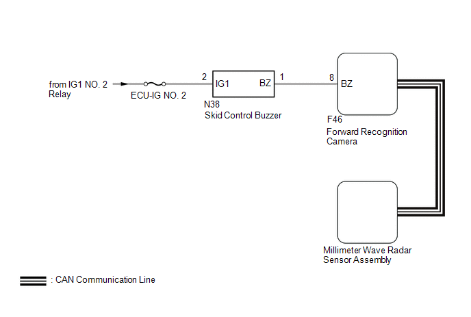
The millimeter wave radar sensor assembly is connected to the forward recognition camera via CAN communication.
The millimeter wave radar sensor assembly operates the pre-collision alarm by sending a buzzer request signal to the skid control buzzer.
If the millimeter wave radar sensor assembly detects a malfunction in the skid control buzzer circuit, it stores DTC C1A4A.
|
DTC No. |
Detection Item |
DTC Detection Condition |
Trouble Area |
|---|---|---|---|
|
C1A4A |
Skid Control Buzzer Circuit |
When the ignition switch is ON and the pre-collision alarm is operating, either of the following conditions is met:
|
|
WIRING DIAGRAM
CAUTION / NOTICE / HINT
NOTICE:
- Inspect the fuses for circuits related to this system before performing the following procedure.
- When replacing the millimeter wave radar sensor assembly, always replace it with a new one.
- When the millimeter wave radar sensor assembly is replaced with a new
one, adjustment of the radar sensor beam axis must be performed.
Click here
.gif)
- If the forward recognition camera has been replaced with a new one,
be sure to perform forward recognition axis adjustment.
Click here
- When a malfunction occurs in the communication line to the forward recognition
camera, U023A and/or U1002 is output. If a DTC related to the CAN communication
line is output, first troubleshoot the CAN communication line.
Click here
PROCEDURE
|
1. |
CHECK FOR DTCs (PRE-COLLISION SYSTEM) |
(a) Clear the DTCs.
Click here
(b) Perform the Active Test according to the display on the Techstream.
Click here
NOTICE:
Perform the Active Test for 1 second or more.
HINT:
Performing the Active Test for 1 second or more causes DTC C1A4A to be stored if the DTC detection conditions are met.
Body Electrical > Pre-Collision 2 > Data List|
Tester Display |
Measurement Item |
Range |
Normal Condition |
Diagnostic Note |
|---|---|---|---|---|
|
PCS Crash Alarm Buzzer |
Skid control buzzer status |
ON or OFF |
ON: Skid control buzzer sounding OFF: Skid control buzzer not sounding |
- |
(c) Check for DTCs.
Click here
|
Result |
Proceed to |
|---|---|
|
DTC C1A4A is not output |
A |
|
DTC C1A4A is output |
B |
| A | .gif) |
USE SIMULATION METHOD TO CHECK |
|
.gif)
|
2. |
CHECK TERMINAL VOLTAGE |
|
(a) Disconnect the skid control buzzer connector. |
|
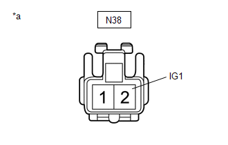
(b) Measure the voltage according to the value(s) in the table below.
Standard Voltage:
|
Tester Connection |
Switch Condition |
Specified Condition |
|---|---|---|
|
N38-2 (IG1) - Body ground |
Ignition switch ON |
11 to 14 V |
|
Ignition switch off |
Below 1 V |
(c) Connect the skid control buzzer connector.
| NG | |
REPAIR OR REPLACE HARNESS OR CONNECTOR (SKID CONTROL BUZZER - BATTERY) |
|
|
3. |
CHECK HARNESS AND CONNECTOR (SKID CONTROL BUZZER - FORWARD RECOGNITION CAMERA) |
(a) Disconnect the N38 skid control buzzer connector.
(b) Disconnect the F46 forward recognition camera connector.
(c) Measure the resistance according to the value(s) in the table below.
Standard Resistance:
|
Tester Connection |
Condition |
Specified Condition |
|---|---|---|
|
N38-1 (BZ) - F46-8 (BZ) |
Always |
Below 1 Ω |
|
N38-1 (BZ) or F46-8 (BZ) - Body ground |
Always |
10 kΩ or higher |
(d) Connect the F46 forward recognition camera connector.
(e) Connect the N38 skid control buzzer connector.
| OK | |
GO TO STEP 6 |
|
|
4. |
REPAIR OR REPLACE HARNESS OR CONNECTOR (SKID CONTROL BUZZER - FORWARD RECOGNITION CAMERA) |
(a) Repair or replace the harness or connector.
|
|
5. |
CHECK FOR DTCs (PRE-COLLISION SYSTEM) |
(a) Clear the DTCs.
Click here
(b) Perform the Active Test according to the display on the Techstream.
Click here
NOTICE:
Perform the Active Test for 1 second or more.
HINT:
Performing the Active Test for 1 second or more causes DTC C1A4A to be stored if the DTC detection conditions are met.
Body Electrical > Pre-Collision 2 > Data List|
Tester Display |
Measurement Item |
Range |
Normal Condition |
Diagnostic Note |
|---|---|---|---|---|
|
PCS Crash Alarm Buzzer |
Skid control buzzer status |
ON or OFF |
ON: Skid control buzzer sounding OFF: Skid control buzzer not sounding |
- |
(c) Check for DTCs.
Click here
|
Result |
Proceed to |
|---|---|
|
DTC C1A4A is not output |
A |
|
DTC C1A4A is output |
B |
| A | |
END |
|
|
6. |
INSPECT SKID CONTROL BUZZER (CONFIRM BUZZER OPERATION) |
(a) Turn the ignition switch to ON.
(b) Check if the skid control buzzer is sounding.
|
Result |
Proceed to |
|---|---|
|
The skid control buzzer does not sound when the ignition switch is ON |
A |
|
The skid control buzzer sounds continuously when the ignition switch is ON |
B |
| B | |
GO TO STEP 8 |
|
|
7. |
INSPECT SKID CONTROL BUZZER (UNIT INSPECTION) |
(a) Remove the skid control buzzer.
Click here
(b) Inspect the skid control buzzer.
Click here
|
Result |
Proceed to |
|---|---|
|
Skid control buzzer is abnormal |
A |
|
Skid control buzzer is normal |
B |
| B | |
GO TO STEP 9 |
|
|
8. |
REPLACE SKID CONTROL BUZZER |
(a) Replace the skid control buzzer.
Click here
|
|
9. |
CHECK FOR DTCs (PRE-COLLISION SYSTEM) |
(a) Clear the DTCs.
Click here
(b) Perform the Active Test according to the display on the Techstream.
Click here
NOTICE:
Perform the Active Test for 1 second or more.
HINT:
Performing the Active Test for 1 second or more causes DTC C1A4A to be stored if the DTC detection conditions are met.
Body Electrical > Pre-Collision 2 > Data List|
Tester Display |
Measurement Item |
Range |
Normal Condition |
Diagnostic Note |
|---|---|---|---|---|
|
PCS Crash Alarm Buzzer |
Skid control buzzer status |
ON or OFF |
ON: Skid control buzzer sounding OFF: Skid control buzzer not sounding |
- |
(c) Check for DTCs.
Click here
|
Result |
Proceed to |
|---|---|
|
DTC C1A4A is not output |
A |
|
DTC C1A4A is output |
B |
| A | |
END |
|
|
10. |
REPLACE FORWARD RECOGNITION CAMERA |
(a) Replace the forward recognition camera.
Click here
(b) Perform forward recognition axis adjustment.
Click here
|
|
11. |
CHECK FOR DTCs (PRE-COLLISION SYSTEM) |
(a) Clear the DTCs.
Click here
(b) Perform the Active Test according to the display on the Techstream.
Click here
NOTICE:
Perform the Active Test for 1 second or more.
HINT:
Performing the Active Test for 1 second or more causes DTC C1A4A to be stored if the DTC detection conditions are met.
Body Electrical > Pre-Collision 2 > Data List|
Tester Display |
Measurement Item |
Range |
Normal Condition |
Diagnostic Note |
|---|---|---|---|---|
|
PCS Crash Alarm Buzzer |
Skid control buzzer status |
ON or OFF |
ON: Skid control buzzer sounding OFF: Skid control buzzer not sounding |
- |
(c) Check for DTCs.
Click here
|
Result |
Proceed to |
|---|---|
|
DTC C1A4A is not output |
A |
|
DTC C1A4A is output |
B |
| A | |
END (FORWARD RECOGNITION CAMERA WAS DEFECTIVE) |
|
|
12. |
REPLACE MILLIMETER WAVE RADAR SENSOR ASSEMBLY |
(a) Replace the millimeter wave radar sensor assembly.
Click here
(b) Adjust the millimeter wave radar sensor assembly.
Click here
|
|
13. |
CLEAR DTC (PRE-COLLISION SYSTEM) |
(a) Clear the DTCs.
Click here
| NEXT | |
END (MILLIMETER WAVE RADAR SENSOR ASSEMBLY WAS DEFECTIVE) |