Toyota Tacoma (2015-2018) Service Manual: Removal
REMOVAL
PROCEDURE
1. REMOVE FUEL PUMP ASSEMBLY (for High Pressure)
(See page .gif) )
)
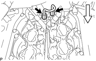
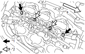
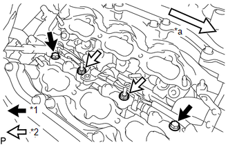
2. REMOVE NO. 2 FUEL PIPE SUB-ASSEMBLY
(a) Loosen the 2 union nuts and remove the No. 2 fuel pipe sub-assembly from the fuel delivery pipe RH and fuel delivery pipe sub-assembly LH.
 Text in Illustration
.png) |
Front |
3. REMOVE FUEL DELIVERY PIPE ASSEMBLY LH (FUEL PRESSURE SENSOR)
NOTICE:
- Do not remove the fuel pressure sensor from the fuel delivery pipe assembly LH.
- If a fuel pressure sensor is removed, replace the fuel delivery pipe assembly LH (fuel pressure sensor) with a new one.
|
(a) Disconnect the 2 connectors. |
|
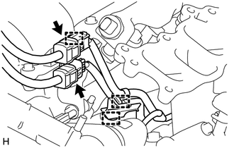
(b) Disengage the 3 clamps and disconnect the No. 6 engine wire and No. 7 engine wire.
|
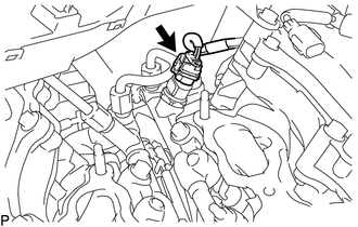
(c) Disconnect the fuel pressure sensor connector. NOTICE: Do not pull the wire harness of the fuel pressure sensor excessively. |
|
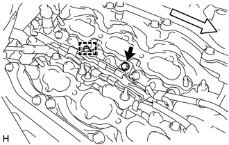
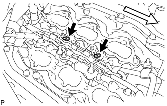
(d) Remove the bolt.
 Text in Illustration
|
|
Front |
(e) Disengage the clamp and disconnect the No. 7 engine wire.
|
(f) Remove the 2 bolts and 2 nuts. Text in Illustration
|
|
(g) Using an E8 "TORX" socket wrench, remove the 2 stud bolts from the cylinder head LH.
 Text in Illustration
|
|
Front |
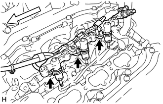
(h) With the connectors still connected, disconnect the fuel delivery pipe assembly LH.
 Text in Illustration
|
|
Front |
NOTICE:
- Make sure that the fuel delivery pipe is disconnected from the fuel delivery pipe assembly LH.
- Be extremely careful not to touch or strike the tips of the fuel injector assemblies.
- Pull and remove the fuel delivery pipe in a straight line without tilting it.
(i) Disconnect the 3 fuel injector connectors and remove the No. 7 engine wire.
4. REMOVE FUEL DELIVERY PIPE RH
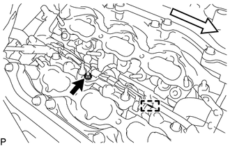
(a) Remove the bolt.
 Text in Illustration
|
|
Front |
(b) Disengage the clamp and disconnect the No. 6 engine wire.
|
(c) Remove the 2 bolts and 2 nuts. Text in Illustration
|
|
(d) With the connectors still connected, disconnect the fuel delivery pipe RH.
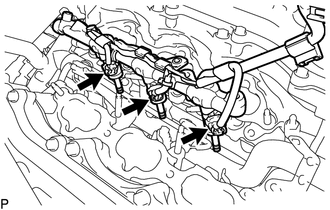 Text in Illustration
|
|
Front |
NOTICE:
- Be extremely careful not to touch or strike the tips of the fuel injector assemblies.
- Pull and remove the fuel delivery pipe in a straight line without tilting it.
(e) Disconnect the 3 injector connectors and remove the No. 6 engine wire.
5. REMOVE FUEL INJECTOR ASSEMBLY
|
(a) Fix the fuel delivery pipe in a vise between aluminum plates. NOTICE:
|
|
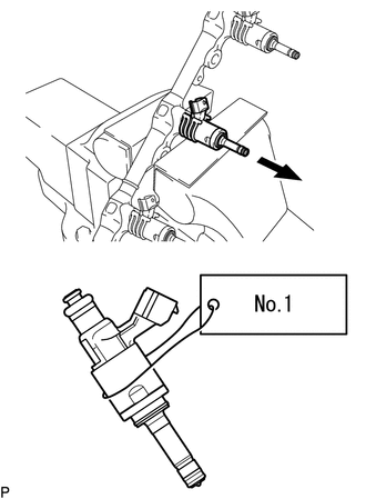
(b) Remove the fuel injector assemblies from the fuel delivery pipe assembly LH and fuel delivery pipe RH.
NOTICE:
- When removing an injector, pull the injector straight out to avoid damaging the O-ring seal surfaces of the fuel delivery pipe assembly LH and fuel delivery pipe RH.
- After removing the fuel injector assembly, check that the O-ring, No. 1 fuel injector back-up ring and No. 3 fuel injector back-up ring are not remaining on the fuel delivery pipe. If any of the parts remain on the fuel delivery pipe, remove them.
- Attach a label to the removed fuel injector assembly to distinguish it from other cylinders.
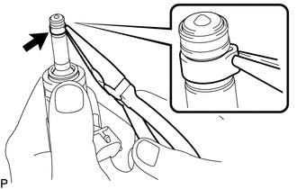
(c) Remove the nozzle holder clamps from the injectors.
(d) Using needle-nose pliers, remove the No. 3 fuel injector back-up ring from the fuel injector assembly.
NOTICE:
Do not damage the part contacting the O-ring.
(e) Remove the O-ring and No. 1 fuel injector back-up ring.
(f) Remove the C-rings and injector vibration insulators from the fuel injector assemblies.
6. REMOVE FUEL INJECTOR SEAL
|
(a) Using the tips of a pair of needle nose pliers, pinch and pull one of the fuel injector seals at several points to stretch it. Repeat this for the other fuel injector seal. NOTICE:
|
|
(b) Remove the fuel injector seal from the fuel injector assembly.
 Inspection
INSPECTION
PROCEDURE
1. INSPECT FUEL INJECTOR ASSEMBLY
NOTICE:
This inspection aims at inspecting the fuel injectors for opens or shorts, because
the fuel injectors of this vehicle are a high-pr ...
 Installation
INSTALLATION
CAUTION / NOTICE / HINT
HINT:
Perform "Inspection After Repairs" after replacing the fuel injector assembly
(See page ).
PROCEDURE
1. INSTALL FUEL INJECTOR SEAL
...
Other materials:
Removal
REMOVAL
PROCEDURE
1. REMOVE STEERING PAD
(See page
)
2. REMOVE STEERING WHEEL ASSEMBLY
3. REMOVE LOWER STEERING COLUMN COVER
4. REMOVE UPPER STEERING COLUMN COVER
5. REMOVE SPIRAL CABLE SUB-ASSEMBLY WITH SENSOR
(a) Slide the slider and disconnect the airbag connect ...
Removal
REMOVAL
PROCEDURE
1. REMOVE INTAKE AIR SURGE TANK ASSEMBLY
(See page )
2. DISCONNECT NO. 2 FUEL TUBE SUB-ASSEMBLY
(a) Disengage the 2 clamps.
(b) Disconnect the No. 2 fuel tube sub-assembly from the fuel tube sub-assembly
(See page ).
...
System Diagram
SYSTEM DIAGRAM
Communication Table
Sender ECU
Receiver ECU
Signal
Line
*1: for Vacuum Brake Booster
*2: for Hydraulic Brake Booster
Forward Recognition Camera
Combination Meter Assembly
...
