DESCRIPTION
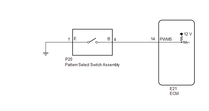
The ECM memory contains the programs for the normal and PWR shift patterns.
By following the programs corresponding to the signals from the pattern select switch assembly, park/neutral position switch and other various sensors, the ECM switches the shift solenoid valves on and off, and controls the transmission gear ratio.
WIRING DIAGRAM
PROCEDURE
|
1. |
INSPECT PATTERN SELECT SWITCH ASSEMBLY |
|
(a) Remove the pattern select switch assembly (See page
|
|
.gif) ).
).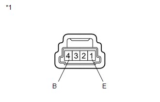
(b) Measure the resistance according to the value(s) in the table below.
Standard Resistance:
|
Tester Connection |
Switch Condition |
Specified Condition |
|---|---|---|
|
1 (E) - 4 (B) |
Pattern select switch assembly pushed |
Below 1 Ω |
|
1 (E) - 4 (B) |
Pattern select switch assembly not pushed |
10 kΩ or higher |
|
*1 |
Pattern Select Switch Assembly |
| NG | .gif) |
REPLACE PATTERN SELECT SWITCH ASSEMBLY |
|
.gif)
|
2. |
CHECK HARNESS AND CONNECTOR (PATTERN SELECT SWITCH ASSEMBLY - BODY GROUND) |
|
(a) Disconnect the pattern select switch assembly connector. |
|
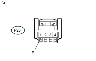
(b) Measure the resistance according to the value(s) in the table below.
Standard Resistance:
|
Tester Connection |
Condition |
Specified Condition |
|---|---|---|
|
P20-1 (E) - Body ground |
Always |
Below 1 Ω |
|
*a |
Front view of wire harness connector (to Pattern Select Switch Assembly)) |
| NG | |
REPAIR OR REPLACE HARNESS OR CONNECTOR |
|
|
3. |
CHECK HARNESS AND CONNECTOR (PATTERN SELECT SWITCH ASSEMBLY - ECM) |
|
(a) Disconnect the ECM connector. |
|
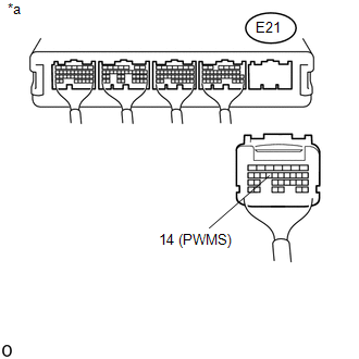
(b) Measure the resistance according to the value(s) in the table below.
Standard Resistance:
|
Tester Connection |
Switch Condition |
Specified Condition |
|---|---|---|
|
E21-14 (PWMS) - Body ground |
Pattern select switch assembly pushed |
Below 1 Ω |
|
E21-14 (PWMS) - Body ground |
Pattern select switch assembly not pushed |
10 kΩ or higher |
|
*a |
Rear view of wire harness connector (to ECM) |
| OK | |
PROCEED TO NEXT SUSPECTED AREA SHOWN IN PROBLEM SYMPTOMS TABLE |
| NG | |
REPAIR OR REPLACE HARNESS OR CONNECTOR |