Inspection
INSPECTION
PROCEDURE
1. INSPECT OUTER MIRROR SWITCH ASSEMBLY
(a) Check the mirror select switch and mirror surface adjust switch.
|
(1) Turn the mirror select switch to the L position. Text in Illustration
|
|
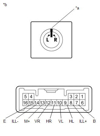
(2) Measure the resistance according to the value(s) in the table below.
Standard Resistance (for left side):
|
Tester Connection |
Condition |
Specified Condition |
|---|---|---|
|
10 (VL) - 7 (B) 13 (M+) - 15 (E) |
Up |
Below 1 Ω |
|
Off |
10 kΩ or higher |
|
|
10 (VL) - 15 (E) 13 (M+) - 7 (B) |
Down |
Below 1 Ω |
|
Off |
10 kΩ or higher |
|
|
9 (HL) - 7 (B) 13 (M+) - 15 (E) |
Left |
Below 1 Ω |
|
Off |
10 kΩ or higher |
|
|
9 (HL) - 15 (E) 13 (M+) - 7 (B) |
Right |
Below 1 Ω |
|
Off |
10 kΩ or higher |
(3) Turn the mirror select switch to the R position.
(4) Measure the resistance according to the value(s) in the table below.
Standard Resistance (for right side):
|
Tester Connection |
Condition |
Specified Condition |
|---|---|---|
|
12 (VR) - 7 (B) 13 (M+) - 15 (E) |
Up |
Below 1 Ω |
|
Off |
10 kΩ or higher |
|
|
12 (VR) - 15 (E) 13 (M+) - 7 (B) |
Down |
Below 1 Ω |
|
Off |
10 kΩ or higher |
|
|
11 (HR) - 7 (B) 13 (M+) - 15 (E) |
Left |
Below 1 Ω |
|
Off |
10 kΩ or higher |
|
|
11 (HR) - 15 (E) 13 (M+) - 7 (B) |
Right |
Below 1 Ω |
|
Off |
10 kΩ or higher |
If the result is not as specified, replace the outer mirror switch assembly.
(b) Check the switch illumination.
(1) Apply battery voltage between the terminals of the light and check the operation of the light.
OK:
|
Measurement Connection |
Specified Condition |
|---|---|
|
Battery positive (+) → Terminal 8 (ILL+) |
Light comes on |
|
Battery negative (-) → Terminal 14 (ILL-) |
If the result is not as specified, replace the outer mirror switch assembly.