DESCRIPTION
Refer to DTCs C1401 and C1402 (See page .gif) ).
).
|
DTC Code |
DTC Detection Condition |
Trouble Area |
|---|---|---|
|
C1405 C1406 |
Either condition is met:
|
|
HINT:
- DTC C1405 is for the front speed sensor RH.
- DTC C1406 is for the front speed sensor LH.
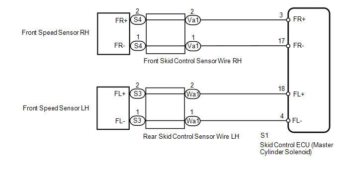
WIRING DIAGRAM
CAUTION / NOTICE / HINT
NOTICE:
- When replacing the skid control ECU (master cylinder solenoid), perform
calibration (See page
).
- Check the speed sensor signal after replacement (See page
).
PROCEDURE
|
1. |
CHECK HARNESS AND CONNECTOR (MOMENTARY INTERRUPTION) |
(a) Using the Techstream, check for any momentary interruption in the wire harness
and connector corresponding to the DTC (See page
).
|
Tester Display |
Measurement Item/Range |
Normal Condition |
Diagnostic Note |
|---|---|---|---|
|
FR Speed Open |
Front speed sensor RH open detection/ Error or Normal |
Normal |
- |
|
FL Speed Open |
Front speed sensor LH open detection/ Error or Normal |
Normal |
- |
OK:
Normal (there are no momentary interruptions).
HINT:
Perform the above inspection before removing the sensor and connector.
| NG | .gif) |
GO TO STEP 4 |
|
.gif)
|
2. |
READ VALUE USING TECHSTREAM (FRONT SPEED SENSOR) |
| NG | |
GO TO STEP 4 |
|
|
3. |
RECONFIRM DTC |
(a) Clear the DTCs (See page
).
(b) Turn the ignition switch off.
(c) Start the engine.
(d) Drive the vehicle at a speed of 40 km/h (25 mph) or more for at least 60 seconds.
(e) Check if the same DTC is output (See page
).
|
Result |
Proceed to |
|---|---|
|
DTCs C1405 and C1406 are not output |
A |
|
DTCs C1405 and/or C1406 are output |
B |
| A | |
USE SIMULATION METHOD TO CHECK |
| B | |
REPLACE MASTER CYLINDER SOLENOID |
|
4. |
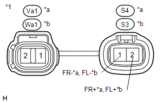
INSPECT SKID CONTROL SENSOR WIRE |
(a) Remove the skid control sensor wire.
|
(b) Measure the resistance according to the value(s) in the table below. Standard Resistance: RH
|
|
| NG | |
REPLACE SKID CONTROL SENSOR WIRE |
|
|
5. |
CHECK HARNESS AND CONNECTOR (SKID CONTROL ECU - FRONT SPEED SENSOR) |
(a) Install the skid control sensor wire.
(b) Disconnect the S1 skid control ECU (master cylinder solenoid) connector.
(c) Disconnect the S4 and/or S3 front speed sensor connector.
(d) Measure the resistance according to the value(s) in the table below.
Standard Resistance:
RH|
Tester Connection |
Condition |
Specified Condition |
|---|---|---|
|
S1-3 (FR+) - S4-2 (FR+) |
Always |
Below 1 Ω |
|
S1-3 (FR+) - Body ground |
Always |
10 kΩ or higher |
|
S1-17 (FR-) - S4-1 (FR-) |
Always |
Below 1 Ω |
|
S1-17 (FR-) - Body ground |
Always |
10 kΩ or higher |
|
Tester Connection |
Condition |
Specified Condition |
|---|---|---|
|
S1-18 (FL+) - S3-2 (FL+) |
Always |
Below 1 Ω |
|
S1-18 (FL+) - Body ground |
Always |
10 kΩ or higher |
|
S1-4 (FL-) - S3-1 (FL-) |
Always |
Below 1 Ω |
|
S1-4 (FL-) - Body ground |
Always |
10 kΩ or higher |
| NG | |
REPAIR OR REPLACE HARNESS OR CONNECTOR |
|
|
6. |
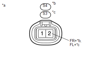
INSPECT SKID CONTROL ECU (FR+, FL+ TERMINAL) |
(a) Disconnect the S4 and/or S3 front speed sensor connector.
(b) Connect the S1 skid control ECU (master cylinder solenoid) connector.
|
(c) Measure the voltage according to the value(s) in the table below. Standard Voltage: RH
|
|
| OK | |
REPLACE FRONT SPEED SENSOR |
| NG | |
REPLACE MASTER CYLINDER SOLENOID |