DESCRIPTION
The IG circuit is the power source for the tire pressure warning ECU and receiver.
WIRING DIAGRAM
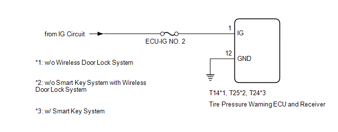
CAUTION / NOTICE / HINT
NOTICE:
- When replacing the tire pressure warning ECU and receiver, read the transmitter IDs stored in the old ECU using the Techstream and write them down before removal.
- It is necessary to perform initialization (See page
.gif) ) after registration (See page
) of the transmitter IDs into the tire
pressure warning ECU and receiver if the ECU has been replaced.
) after registration (See page
) of the transmitter IDs into the tire
pressure warning ECU and receiver if the ECU has been replaced.
HINT:
Inspect the fuses for circuits related to this system before performing the following procedure.
PROCEDURE
|
1. |
CHECK HARNESS AND CONNECTOR (ECU - BATTERY AND BODYGROUND) |
|
(a) Disconnect the T14*1, T25*2, T24*3 tire pressure warning ECU and receiver connector. |
|
.png)
(b) Measure the voltage according to the value(s) in the table below.
Standard Voltage:
|
Tester Connection |
Switch Condition |
Specified Condition |
|---|---|---|
|
T14-1 (IG) - Body ground*1 T25-1 (IG) - Body ground*2 T24-1 (IG) - Body ground*3 |
Ignition switch ON |
10 to 16 V |
|
Ignition switch off |
Below 1 V |
(c) Measure the resistance according to the value(s) in the table below.
Standard Resistance:
|
Tester Connection |
Condition |
Specified Condition |
|---|---|---|
|
T14-12 (GND) - Body ground*1 T25-12 (GND) - Body ground*2 T24-12 (GND) - Body ground*3 |
Always |
Below 1 Ω |
|
*a |
Front view of wire harness connector (to Tire Pressure Warning ECU and Receiver) |
- *1: w/o Wireless Door Lock System
- *2: w/o Smart Key System with Wireless Door Lock System
- *3: w/ Smart Key System
| OK | .gif) |
REPLACE TIRE PRESSURE WARNING ECU AND RECEIVER |
| NG | |
REPAIR OR REPLACE HARNESS OR CONNECTOR |