DTC CHECK / CLEAR
1. START DIAGNOSTIC MODE
HINT:
- Illustrations may differ from the actual vehicle screen depending on the device settings and options. Therefore, some detailed areas may not be shown exactly the same as on the actual vehicle screen.
- If the system cannot enter diagnostic mode, inspect all AVC-LAN communication
components and repair or replace problem parts (See page
.gif) ).
). - After the ignition switch is turned to ON, check that the map is displayed before starting diagnostic mode. Otherwise, some items cannot be checked.
(a) Start the engine.
(b) While pressing and holding the "AUDIO" switch, operate the light control switch: Off → Tail → Off → Tail → Off → Tail → Off.
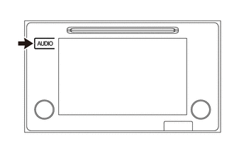
(c) Diagnostic mode starts and the "Service Menu" screen will be displayed. Service inspection starts automatically and the result will be displayed.
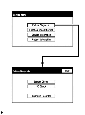
2. FAILURE DIAGNOSIS
(a) The "Failure Diagnosis" screen will be displayed by pressing the "Failure Diagnosis" switch on the "Service Menu" screen.
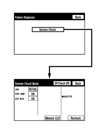
3. SYSTEM CHECK
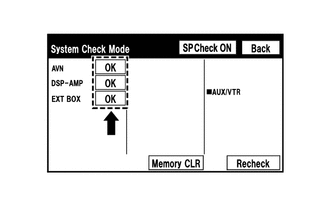
(a) The "System Check Mode" screen will be displayed by pressing the "System Check" switch on the "Failure Diagnosis" screen.
4. CHECK DTC (CHECK USING SYSTEM CHECK MODE SCREEN)
HINT:
- When "NCON" is displayed for all devices connected using the AVC-LAN,
or when all device names are not displayed, check if there is a short circuit
in the AVC-LAN or devices connected to the AVC-LAN. Repair or replace parts
as necessary (See page ).
(a) System check mode screen description
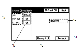 Screen Description
|
Display |
Content |
|---|---|
|
*a: Device Name List No. 1 |
|
|
*b: Check Result |
Result codes for all devices are displayed. |
|
*c: Memory Clear |
|
|
*d: Recheck |
|
|
*e: Device Name List No. 2 |
|
|
Name |
Component |
Connection Method |
|---|---|---|
|
AVN |
Navigation receiver assembly |
- |
|
EXT BOX |
Stereo component tuner assembly |
Communication line for LVDS |
|
DSP-AMP |
Stereo component amplifier assembly |
Communication line for AVC-LAN |
|
Result |
Meaning |
Action |
|---|---|---|
|
OK |
The device does not respond with a DTC. |
- |
|
DETAIL |
The device responds with a DTC. |
Look up the DTC in "Unit Check Mode". |
|
NCON |
The device was previously present, but does not respond in diagnostic mode. |
- Check power supply wire harness of the device. - Check the AVC-LAN of the device. |
|
NRES |
The device responds in diagnostic mode, but gives no DTC information. |
- Check power supply wire harness of the device. - Check the AVC-LAN of the device. |
|
Name |
Component |
Connection Method |
|---|---|---|
|
AUX/VTR |
No. 1 stereo jack adapter assembly |
Vehicle wire harness |
(b) Unit check mode screen description
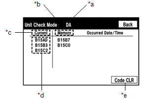 Screen Description
|
Display |
Content |
|---|---|
|
*a: Device name |
Target device |
|
*b: History DTC |
Diagnostic memory results and stored DTCs are displayed. |
|
*c: Current DTC |
DTCs output in the service check are displayed. |
|
*d: DTC |
DTC (Diagnostic Trouble Code) |
|
*e: Diagnosis clear switch |
Pushing this switch for 3 seconds clears the diagnostic memory data of the target device (Both response to diagnostic system check result and the displayed data are cleared.). |
HINT:
- This screen is updated once per second.
- A maximum of 6 DTCs can be displayed for history and present DTCs.
(c) Read the system check result.
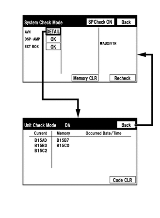
(1) If the check result is "DETAIL", touch the displayed check result to view the results on the "Unit Check Mode" screen and record them.
NOTICE:
A maximum of 6 DTCs can be displayed for history and present DTCs on the "Unit check mode" screen. Therefore, when 6 DTCs are displayed, troubleshoot those DTCs first and then check the "Unit check mode" screen again to see if any other DTCs are displayed.
HINT:
- When all results are "OK", this means that no DTCs are present.
- When proceeding to view the results of another device, press the "Back" switch to return to the "System Check Mode" screen. Repeat the step above to view the results of other devices.
(2) Check the details of the DTCs (See page
).
5. DTC CLEAR/RECHECK (CLEAR USING SYSTEM CHECK MODE SCREEN)
(a) Clear DTC
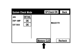
(1) Press the "Memory CLR" switch for 3 seconds.
(2) Confirm that the check results are cleared.
HINT:
- To clear the DTC for a specific device, clear the DTC using the "Unit Check Mode" screen.
- When clearing a DTC using the "Unit Check Mode" screen, press the "Code CLR" switch for 3 seconds.
(b) Recheck
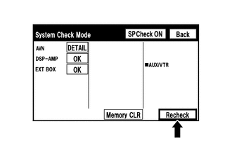
(1) Press the "Recheck" switch.
(2) Confirm that all diagnostic codes are "OK" when the check results are displayed. If a code other than "OK" is displayed, troubleshoot again.
HINT:
When a DTC was cleared using the "Unit Check Mode" screen, press the "Back" switch to return to the "System Check Mode" screen and perform this operation.
6. FINISH DIAGNOSTIC MODE
(a) Turn the ignition switch off.