Toyota Tacoma (2015-2018) Service Manual: Air Conditioning Amplifier
Components
COMPONENTS
ILLUSTRATION
Installation
INSTALLATION
PROCEDURE
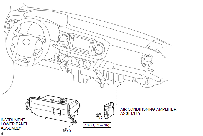
1. INSTALL AIR CONDITIONING AMPLIFIER ASSEMBLY
(a) Install the air conditioner amplifier assembly with the 2 bolts.
Torque:
7.0 N·m {71 kgf·cm, 62 in·lbf}
(b) Connect the 2 connectors.
2. INSTALL INSTRUMENT LOWER PANEL ASSEMBLY
.gif)
3. INSTALL LOWER NO. 2 INSTRUMENT PANEL AIRBAG ASSEMBLY
(See page )
Removal
REMOVAL
PROCEDURE
1. REMOVE LOWER NO. 2 INSTRUMENT PANEL AIRBAG ASSEMBLY
(See page .gif) )
)
2. REMOVE INSTRUMENT LOWER PANEL ASSEMBLY
3. REMOVE AIR CONDITIONING AMPLIFIER ASSEMBLY
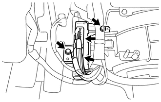
(a) Disconnect the 2 connectors.
(b) Remove the 2 bolts and air conditioning amplifier assembly.
 Air Conditioning
...

Other materials:
Data List / Active Test
DATA LIST / ACTIVE TEST
1. DATA LIST
Using the Techstream to read the Data List allows the values or states of switches,
sensors, actuators and other items to be read without removing any parts. This non-intrusive
inspection can be very useful because intermittent conditions or signals may be ...
System Description
SYSTEM DESCRIPTION
1. FUNCTION DESCRIPTION
(a) ABS (Anti-lock Brake System)
(1) The ABS helps prevent the wheels from locking when the brakes are applied
firmly or when braking on a slippery surface.
(b) EBD (Electronic Brake force Distribution)
(1) The EBD control utilizes ABS, and performs ...
Precaution
PRECAUTION
1. IGNITION SWITCH EXPRESSIONS
(a) The type of ignition switch used on this model differs according to the specifications
of the vehicle. The expressions listed in the table below are used in this section.
Expression
Ignition Switch (Position)
Engine ...
