DESCRIPTION
This No. 1 air conditioning radiator damper servo sub-assembly (for mode switching) is controlled by the air conditioning amplifier assembly and moves the mode damper to the desired position.
|
DTC No. |
DTC Detection Condition |
Trouble Area |
|---|---|---|
|
B1443/43 |
Mode damper position sensor value does not change even if air conditioning amplifier assembly operates mode damper servo motor. |
|
WIRING DIAGRAM
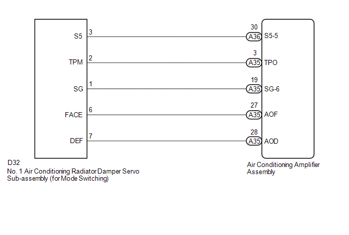
PROCEDURE
|
1. |
READ VALUE USING TECHSTREAM |
(a) Connect the Techstream to the DLC3.
(b) Turn the ignition switch to ON.
(c) Turn the Techstream on.
(d) Operate the mode switch.
(e) Enter the following menus: Body Electrical / Air Conditioner / Data List.
(f) Check the value(s) by referring to the table below.
Air Conditioner|
Tester Display |
Measurement Item/Range |
Normal Condition |
Diagnostic Note |
|---|---|---|---|
|
Air Outlet Damper Position |
Mode damper servo motor actual position / Min.: -14.0% Max.: 113.5% |
FACE: 0.0% DEF: 100.0% |
- |
|
Air Outlet Damper Target |
Mode damper servo motor target position / Min.: -14.0% Max.: 113.5% |
FACE: 0.0% DEF: 100.0% |
- |
OK:
The display is as specified in the Normal Condition column.
|
Result |
Proceed to |
|---|---|
|
NG |
A |
|
OK (When troubleshooting according to Problem Symptoms Table) |
B |
|
OK (When troubleshooting according to the DTC) |
C |
| B | .gif) |
PROCEED TO NEXT SUSPECTED AREA SHOWN IN PROBLEM SYMPTOMS TABLE |
| C | |
REPLACE AIR CONDITIONING AMPLIFIER ASSEMBLY |
|
.gif)
|
2. |
INSPECT NO. 1 AIR CONDITIONING RADIATOR DAMPER SERVO SUB-ASSEMBLY (FOR MODE SWITCHING) |
(a) Remove the No. 1 air conditioning radiator damper servo sub-assembly (for
mode switching) (See page .gif) ).
).
(b) Inspect the No. 1 air conditioning radiator damper servo sub-assembly (for
mode switching) (See page ).
| NG | |
REPLACE NO. 1 AIR CONDITIONING RADIATOR DAMPER SERVO SUB-ASSEMBLY (FOR MODE SWITCHING) |
|
|
3. |
CHECK HARNESS AND CONNECTOR (NO. 1 AIR CONDITIONING RADIATOR DAMPER SERVO SUB-ASSEMBLY - AIR CONDITIONING AMPLIFIER ASSEMBLY) |
(a) Disconnect the D32 No. 1 air conditioning radiator damper servo sub-assembly (for mode switching) connector.
(b) Disconnect the A35 air conditioning amplifier assembly connector.
(c) Measure the resistance according to the value(s) in the table below.
Standard Resistance:
|
Tester Connection |
Condition |
Specified Condition |
|---|---|---|
|
D32-6 (FACE) - A35-27 (AOF) |
Always |
Below 1 Ω |
|
D32-7 (DEF) - A35-28 (AOD) |
Always |
Below 1 Ω |
|
D32-6 (FACE) or A35-27 (AOF) |
Always |
10 kΩ or higher |
|
D32-7 (DEF) or A35-28 (AOD) |
Always |
10 kΩ or higher |
| OK | |
REPLACE AIR CONDITIONING AMPLIFIER ASSEMBLY |
| NG | |
REPAIR OR REPLACE HARNESS OR CONNECTOR |