DESCRIPTION
If any of the following is detected, the ABS warning light remains on.
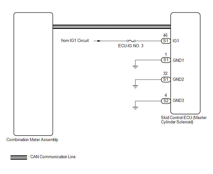
- The skid control ECU (master cylinder solenoid) connectors are disconnected from the skid control ECU (master cylinder solenoid).
- There is a malfunction in the skid control ECU (master cylinder solenoid) internal circuit.
- There is an open in the harness between the combination meter assembly and skid control ECU (master cylinder solenoid).
- The anti-lock brake system is defective.
- The voltage at terminal IG1 is high.
- The rear differential is locked.
HINT:
It may not be possible to use the Techstream when the skid control ECU (master cylinder solenoid) is abnormal.
WIRING DIAGRAM
CAUTION / NOTICE / HINT
NOTICE:
- When replacing the skid control ECU (master cylinder solenoid), perform
calibration (See page
.gif) ).
). - Inspect the fuses for circuits related to this system before performing the following inspection procedure.
PROCEDURE
|
1. |
CHECK THAT SKID CONTROL ECU CONNECTOR IS SECURELY CONNECTED |
(a) Check the skid control ECU (master cylinder solenoid) connector connection.
OK:
The connector is securely connected.
| NG | .gif) |
CONNECT CONNECTOR TO ECU CORRECTLY |
|
.gif)
|
2. |
CHECK DTC |
(a) Check for DTCs (See page
).
|
Result |
Proceed to |
|---|---|
|
DTC is not output |
A |
|
DTC is output |
B |
| B | |
REPAIR CIRCUITS INDICATED BY OUTPUT DTCS |
|
|
3. |
INSPECT BATTERY |
(a) Inspect the battery voltage (See page ).
Standard voltage:
11 to 14 V
| NG | |
CHECK CHARGING SYSTEM |
|
|
4. |
CHECK CAN COMMUNICATION SYSTEM |
(a) Turn the ignition switch off.
(b) Connect the Techstream to the DLC3.
(c) Turn the ignition switch to ON.
(d) Turn the Techstream on.
(e) Select CAN Bus Check from the System Selection Menu screen and follow the
prompts on the screen to inspect the CAN bus (See page
).
OK:
CAN Bus Check indicates no malfunctions in CAN communication.
| NG | |
GO TO CAN COMMUNICATION SYSTEM (HOW TO PROCEED WITH TROUBLESHOOTING) |
|
|
5. |
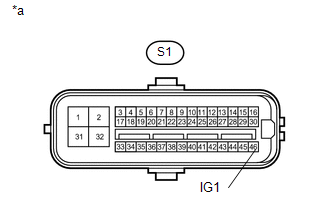
CHECK HARNESS AND CONNECTOR (IG1 TERMINAL) |
(a) Disconnect the skid control ECU (master cylinder solenoid) connector.
|
(b) Measure the voltage according to the value(s) in the table below. Standard Voltage:
|
|
| NG | |
REPAIR OR REPLACE HARNESS OR CONNECTOR |
|
|
6. |
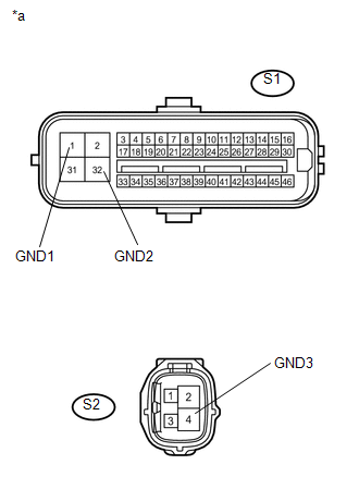
CHECK HARNESS AND CONNECTOR (GND TERMINAL) |
|
(a) Measure the resistance according to the value(s) in the table below. Standard Resistance:
|
|
(b) Reconnect the skid control ECU (master cylinder solenoid) connector.
Result|
Result |
Proceed to |
|---|---|
|
OK (w/ Rear Differential Lock) |
A |
|
OK (w/o Rear Differential Lock) |
B |
|
NG |
C |
|
| C | |
REPAIR OR REPLACE HARNESS OR CONNECTOR |
|
|
7. |
CHECK DIFFERENTIAL SYSTEM |
(a) Reconnect the S1 skid control ECU (master cylinder solenoid) connector.
(b) Connect the Techstream to the DLC3.
(c) Turn the ignition switch to ON.
(d) Turn the Techstream on.
(e) Enter the following menus: Powertrain / Four Wheel Drive / Trouble Codes.
(f) Check for DTCs.
Result|
Result |
Proceed to |
|---|---|
|
DTCs are not output |
A |
|
DTCs are output |
B |
| B | |
GO TO DIFFERENTIAL SYSTEM (DIAGNOSTIC TROUBLE CODE CHART) |
|
|
8. |
READ VALUE USING TECHSTREAM (ABS WARNING LIGHT) |
(a) Reconnect the S1 skid control ECU (master cylinder solenoid) connector.
(b) Connect the Techstream to the DLC3.
(c) Turn the ignition switch to ON.
(d) Turn the Techstream on.
(e) Enter the following menus: Chassis / ABS/VSC/TRAC / Data List.
(f) According to the display on the Techstream, read the Data List.
ABS/VSC/TRAC|
Tester Display |
Measurement Item/Range |
Normal Condition |
Diagnostic Note |
|---|---|---|---|
|
ABS Warning Light |
ABS warning light/ ON or OFF |
OFF |
- |
(g) Check the Techstream display condition of the ABS warning light.
Result|
Result |
Proceed to |
|---|---|
|
Display of the Data List remains OFF |
A |
|
Display of the Data List remains ON |
B |
| A | |
GO TO METER / GAUGE SYSTEM |
| B | |
REPLACE MASTER CYLINDER SOLENOID |