Toyota Tacoma (2015-2018) Service Manual: Terminals Of Ecu
TERMINALS OF ECU
1. BLIND SPOT MONITOR SENSOR LH (MASTER)

|
Terminal No. (Symbol) |
Wiring Color |
Terminal Description |
Condition |
Specified Condition |
|---|---|---|---|---|
|
B12-3 (BIND) - B12-10 (BLGD) |
Y - W-B |
Blind spot monitor main switch indicator signal |
Blind spot monitor main switch indicator illuminated |
11 to 14 V |
|
Blind spot monitor main switch indicator not illuminated |
Below 1 V |
|||
|
B12-4 (OMIL) - B12-10 (BLGD) |
G - W-B |
Outer rear view mirror indicator power source signal RH |
Outer rear view mirror indicator illuminated |
2.5 to 7.5 V |
|
Outer rear view mirror indicator blinks |
Alternating between 0 to 7.5 V |
|||
|
Outer rear view mirror indicator not illuminated |
Below 1 V |
|||
|
B12-5 (BLB) - B12-10 (BLGD) |
LG - W-B |
IG power source signal |
Ignition switch off |
Below 1 V |
|
Ignition switch ON |
11 to 14 V |
|||
|
B12-8 (BSSW) - B12-10 (BLGD) |
GR - W-B |
Blind spot monitor main switch assembly (warning canceling switch assembly) signal |
Ignition switch ON, blind spot monitor main switch assembly (warning canceling switch assembly) on |
11 to 14 V |
|
Ignition switch ON, blind spot monitor main switch assembly (warning canceling switch assembly) off |
Below 1 V |
|||
|
B12-10 (BLGD) - Body Ground |
W-B - Body ground |
Ground |
Always |
Below 1 V |
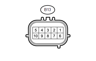
2. BLIND SPOT MONITOR SENSOR RH (SLAVE)
|
Terminal No. (Symbol) |
Wiring Color |
Terminal Description |
Condition |
Specified Condition |
|---|---|---|---|---|
|
B13-3 (BUZ) - B13-10 (BRGD) |
R - W-B |
Rear cross traffic alert buzzer (blind spot monitor buzzer) operation signal |
Rear cross traffic alert buzzer (blind spot monitor buzzer) not sounding |
11 to 14 V |
|
Outer rear view mirror indicator blinks |
Alternating between 0 to 7.5 V |
|||
|
Rear cross traffic alert buzzer (blind spot monitor buzzer) sounding |
Alternating between 0 to 14 V |
|||
|
B13-4 (OMIR) - B13-10 (BRGD) |
SB - W-B |
Outer rear view mirror indicator power source signal LH |
Outer rear view mirror indicator illuminated |
2.5 to 7.5 V |
|
Outer rear view mirror indicator blinks |
Alternating between 0 to 7.5 V |
|||
|
Outer rear view mirror indicator not illuminated |
Below 1 V |
|||
|
B13-5 (BRB) - B13-10 (BRGD) |
LG - W-B |
IG power source signal |
Ignition switch off |
Below 1 V |
|
Ignition switch ON |
11 to 14 V |
|||
|
B13-8 (SPR) - B13-10 (BRGD)*1 |
P - W-B |
Shift position reverse switch signal |
Rear cross traffic alert function is active (vehicle is in reverse) |
11 to 14 V |
|
Rear cross traffic alert function is not active (vehicle is in position other than reverse) |
Below 1 V |
|||
|
B13-10 (BRGD) - Body Ground |
W-B - Body ground |
Ground |
Always |
Below 1 V |
- *1: for Manual Transmission
 Problem Symptoms Table
PROBLEM SYMPTOMS TABLE
HINT:
Use the table below to help determine the cause of problem symptoms. If multiple
suspected areas are listed, the potential causes of the symptoms are listed in order
...
 Diagnosis System
DIAGNOSIS SYSTEM
1. DESCRIPTION
(a) Blind spot monitor data and Diagnostic Trouble Codes (DTCs) can be read from
the Data Link Connector 3 (DLC3) of the vehicle. When the system seems to be malfun ...
Other materials:
Lost Communication With Vehicle Dynamics Control Module (U0122)
DESCRIPTION
This DTC is detected if communication is lost with the skid control ECU (brake
actuator assembly).
DTC No.
Detection Item
DTC Detection Condition
Trouble Area
U0122
Lost Communication with Vehicle Dynamics Contro ...
Vehicle Speed Sensor "A" No Signal (P050031)
DESCRIPTION
Vehicles, which are equipped with ABS (Anti-lock Brake System), detect the vehicle
speed using the skid control ECU (brake actuator assembly) and speed sensors. Each
speed sensor monitors the wheel rotation speed and sends a signal to the skid control
ECU. The skid control ECU con ...
Installation
INSTALLATION
PROCEDURE
1. SET NO. 1 CYLINDER TO TDC/COMPRESSION
2. INSTALL CAMSHAFT TIMING GEAR BOLT
NOTICE:
There are different types of camshaft timing gearbolts. Make sure to check the
identification mark todetermine the tightening torque.
*a
Identification Mark ...
