Toyota Tacoma (2015-2018) Service Manual: Terminals Of Ecu
TERMINALS OF ECU

CHECK MILLIMETER WAVE RADAR SENSOR ASSEMBLY
(a) Measure the voltage and resistance according to the value(s) in the table below.
|
Terminal No. (Symbol) |
Wiring Color |
Terminal Description |
Condition |
Specified Condition |
|---|---|---|---|---|
|
M8-8 (IGB) - M8-1 (SGND) |
LG - W-B |
Power source |
Ignition switch ON |
11 to 14 V |
|
M8-1 (SGND) - Body ground |
W-B - Body ground |
Ground |
Always |
Below 1 Ω |
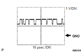
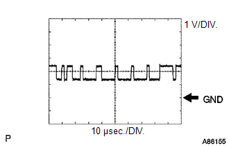
(b) Check for pulses according to the value(s) in the table below.
HINT:
If the waveform is not similar to that shown in the illustration, malfunction of a CAN bus line, terminating resistor or the millimeter wave radar sensor assembly is suspected.
|
Terminal No. (Symbol) |
Wiring Color |
Terminal Description |
Condition |
Specified Condition |
|---|---|---|---|---|
|
M8-3 (CA2H) - M8-1 (SGND) |
W-B - W-B |
CAN communication signal |
Ignition switch ON |
Pulse generation (See waveform 1) |
|
M8-2 (CA2L) - M8-1 (SGND) |
W - W-B |
CAN communication signal |
Ignition switch ON |
Pulse generation (See waveform 2) |
|
M8-5 (CA1P) - M8-1 (SGND) |
B - W-B |
CAN communication signal |
Ignition switch ON |
Pulse generation (See waveform 1) |
|
M8-6 (CA1N) - M8-1 (SGND) |
W - W-B |
CAN communication signal |
Ignition switch ON |
Pulse generation (See waveform 2) |
(1) Waveform 1
|
Item |
Content |
|---|---|
|
Terminal Name |
Between M8-3 (CA2H) and M8-1 (SGND) Between M8-5 (CA1P) and M8-1 (SGND) |
|
Tester Range |
1 V/DIV., 10 ÎĽsec./DIV. |
|
Condition |
Ignition switch ON |
HINT:
The waveform varies depending on the CAN communication signal.
(2) Waveform 2
|
Item |
Content |
|---|---|
|
Terminal Name |
Between M8-2 (CA2L) and M8-1 (SGND) Between M8-6 (CA1N) and M8-1 (SGND) |
|
Tester Range |
1 V/DIV., 10 ÎĽsec./DIV. |
|
Condition |
Ignition switch ON |
HINT:
The waveform varies depending on the CAN communication signal.
NOTICE:
- DTCs may be stored when connectors are disconnected during inspection. Therefore, be sure to clear the DTCs using the Techstream once the inspection has been completed.
- Do not apply excessive force to the F46 forward recognition camera connector.

CHECK FORWARD RECOGNITION CAMERA
(a) Measure the voltage and resistance according to the value(s) in the table below.
|
Terminal No. (Symbol) |
Wiring Color |
Terminal Description |
Condition |
Specified Condition |
|---|---|---|---|---|
|
F46-7 (IGB) - F46-10 (GND) |
BE - W-B |
Power source |
Ignition switch ON |
11 to 14 V |
|
Ignition switch off |
Below 1 V |
|||
|
F46-10 (GND) - Body ground |
W-B - Body ground |
Ground |
Always |
Below 1 Ω |
(b) Check for pulses according to the value(s) in the table below.
HINT:
If the waveform is not similar to that shown in the illustration, malfunction of a CAN bus line, terminating resistor or the forward recognition camera is suspected.
|
Terminal No. (Symbol) |
Wiring Color |
Terminal Description |
Condition |
Specified Condition |
|---|---|---|---|---|
|
F46-5 (CA1P) - F46-10 (GND) |
L - W-B |
CAN communication signal |
Ignition switch ON |
Pulse generation (See waveform 1) |
|
F46-11 (CA1N) - F46-10 (GND) |
W - W-B |
CAN communication signal |
Ignition switch ON |
Pulse generation (See waveform 2) |
|
F46-6 (CANH) - F46-10 (GND) |
B - W-B |
CAN communication signal |
Ignition switch ON |
Pulse generation (See waveform 1) |
|
F46-12 (CANL) - F46-10 (GND) |
W - W-B |
CAN communication signal |
Ignition switch ON |
Pulse generation (See waveform 2) |
(1) Waveform 1
|
Item |
Content |
|---|---|
|
Terminal Name |
Between F46-5 (CA1P) and F46-10 (GND) Between F46-6 (CANH) and F46-10 (GND) |
|
Tester Range |
1 V/DIV., 10 ÎĽsec./DIV. |
|
Condition |
Ignition switch ON |
HINT:
The waveform varies depending on the CAN communication signal.
(2) Waveform 2
|
Item |
Content |
|---|---|
|
Terminal Name |
Between F46-11 (CA1N) and F46-10 (GND) Between F46-12 (CANL) and F46-10 (GND) |
|
Tester Range |
1 V/DIV., 10 ÎĽsec./DIV. |
|
Condition |
Ignition switch ON |
HINT:
The waveform varies depending on the CAN communication signal.
 Problem Symptoms Table
PROBLEM SYMPTOMS TABLE
HINT:
Use the table below to help determine the cause of problem symptoms.
If multiple suspected areas are listed, the potential causes of the symptoms
are lis ...
 Utility
UTILITY
NOTICE:
When replacing the millimeter wave radar sensor assembly, always replace
it with a new one. If a millimeter wave radar sensor assembly which was
installed to another ...
Other materials:
Dtc Check / Clear
DTC CHECK / CLEAR
1. CHECK DTC (for TIRE PRESSURE WARNING ECU AND RECEIVER) (USING TECHSTREAM)
(a) Turn the ignition switch off.
(b) Connect the Techstream to the DLC3.
(c) Turn the ignition switch to ON.
(d) Turn the Techstream on.
(e) Enter the following menus: Chassis / Tire Pressure Monito ...
Satellite Radio Tuner
Components
COMPONENTS
ILLUSTRATION
Removal
REMOVAL
PROCEDURE
1. REMOVE RADIO AND DISPLAY RECEIVER ASSEMBLY WITH BRACKET
(See page )
2. REMOVE NO. 1 NAVIGATION WIRE
(a) Disconnect the 6 connectors to remove the No. 1 navigation wire.
...
Problem Symptoms Table
PROBLEM SYMPTOMS TABLE
HINT:
Use the table below to help determine the cause of problem symptoms.
If multiple suspected areas are listed, the potential causes of the symptoms
are listed in order of probability in the "Suspected Area" column of the
table. Check each sy ...
