Toyota Tacoma (2015-2018) Service Manual: System Diagram
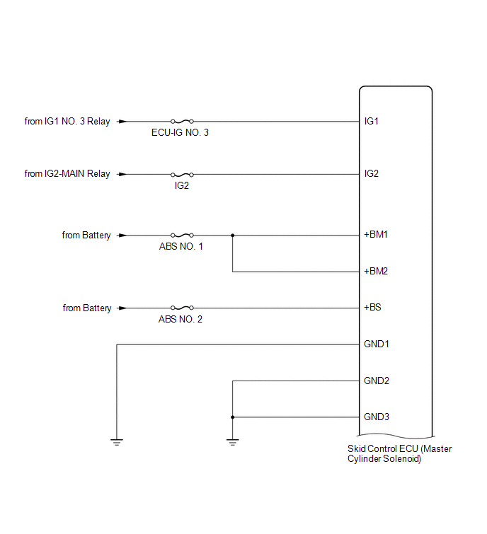
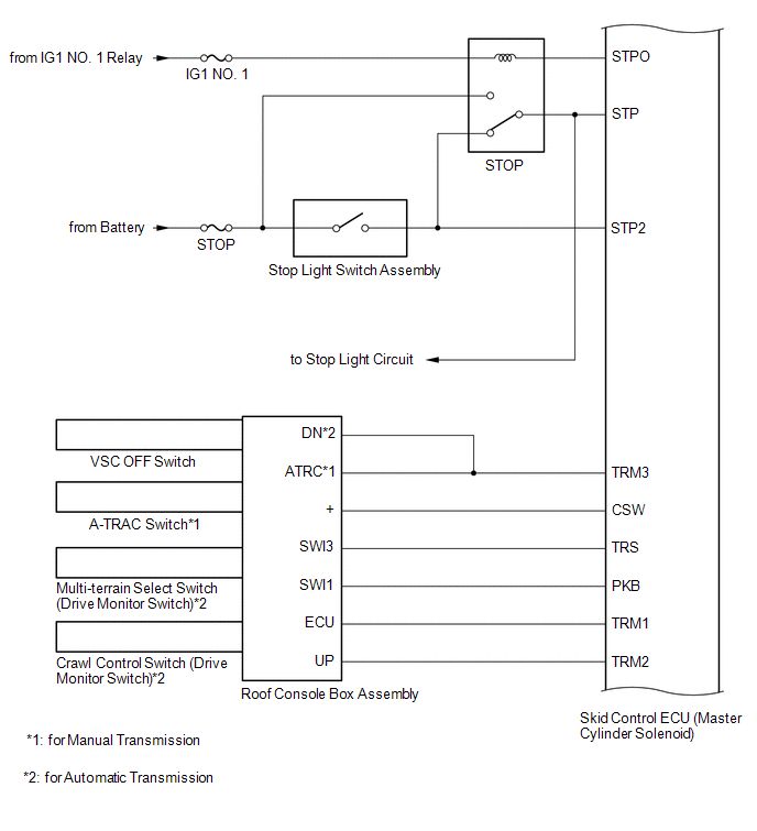
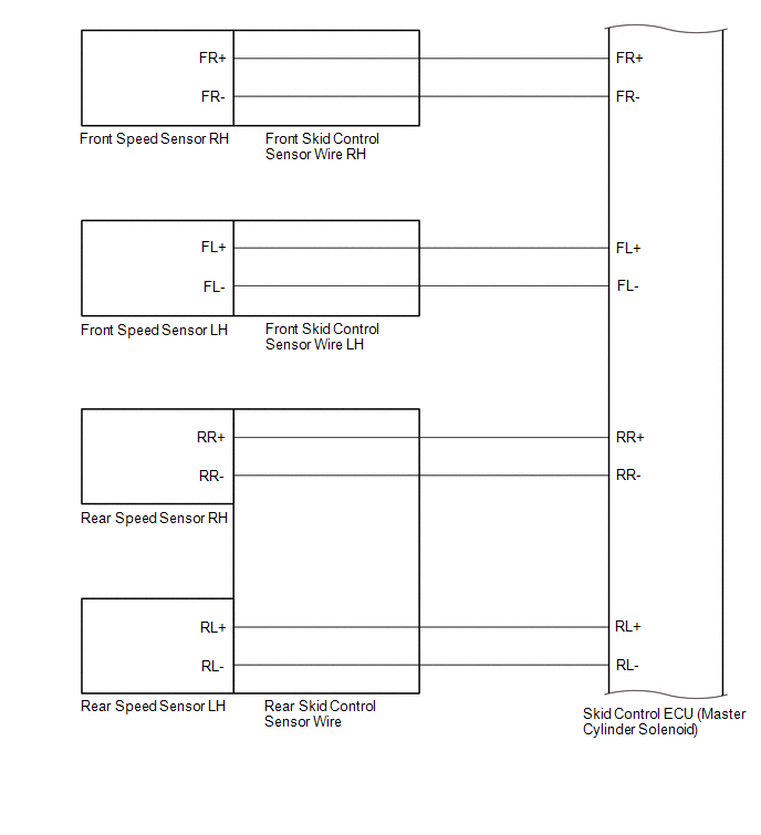
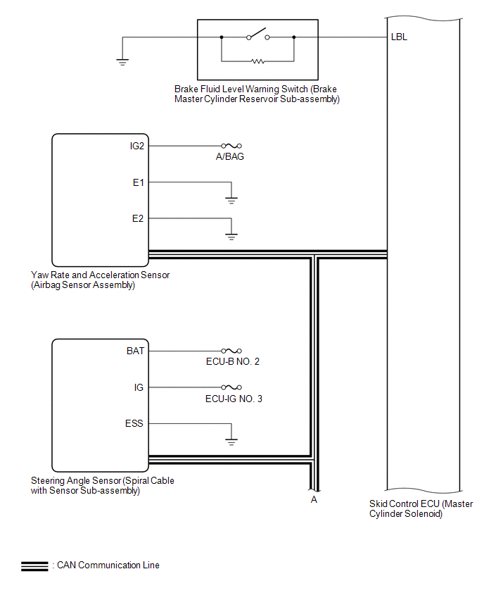
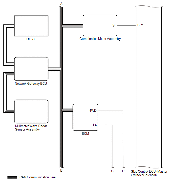
SYSTEM DIAGRAM
|
Transmitting ECU (Transmitter) |
Receiving ECU |
Signals |
Communication Method |
|---|---|---|---|
|
ECM |
Skid control ECU |
|
CAN communication system |
|
Yaw rate and acceleration sensor (Airbag sensor assembly) |
Skid control ECU |
Yaw rate and acceleration signal |
CAN communication system |
|
Steering angle sensor (spiral cable with sensor sub-assembly) |
Skid control ECU |
Steering angle signal |
CAN communication system |
|
Skid control ECU |
ECM |
Throttle opening angle request signal |
CAN communication system |
|
Skid control ECU |
Combination meter assembly |
|
CAN communication system |
|
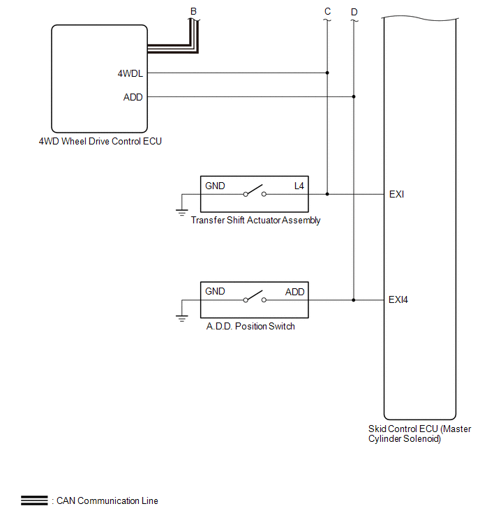
4 wheel drive control ECU (for 4WD or w/ Rear Differential Lock) |
Skid control ECU |
|
CAN communication system |
 System Description
SYSTEM DESCRIPTION
1. SYSTEM DESCRIPTION
HINT:
The skid control ECU is built into the hydraulic brake booster.
(a) ABS (Anti-lock Brake System)
The ABS helps prevent the wheels from locking when ...
 Check For Intermittent Problems
CHECK FOR INTERMITTENT PROBLEMS
1. DESCRIPTION
HINT:
A momentary interruption (open circuit) in the connectors and/or wire harness
between the sensors and ECUs can be detected through the ECU dat ...
Other materials:
Center Airbag Sensor Assembly
Components
COMPONENTS
ILLUSTRATION
On-vehicle Inspection
ON-VEHICLE INSPECTION
PROCEDURE
1. INSPECT AIRBAG SENSOR ASSEMBLY (for Vehicle not Involved in Collision)
(a) Perform a diagnostic system check (See page
).
2. INSPECT AIRBAG SENSOR ASSEMBLY (for Vehicle Involved in Collision a ...
Clearance Sonar Main Switch Circuit
DESCRIPTION
The back sonar or clearance sonar switch assembly is installed at the base of
the driver side of the instrument panel.
When the back sonar or clearance sonar switch assembly is turned on, an on signal
is sent to the clearance warning ECU assembly. The intuitive parking assist syste ...
How To Proceed With Troubleshooting
CAUTION / NOTICE / HINT
HINT:
The ECM of this system is connected to the CAN communication system.
Therefore, before starting troubleshooting, make sure to check that there
is no trouble in the CAN and multiplex communication system.
*: Use the Techstream.
PROCEDURE
...
