Toyota Tacoma (2015-2018) Service Manual: System Diagram
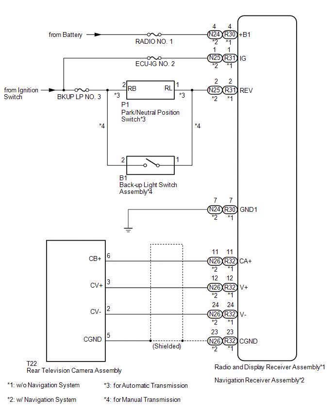
SYSTEM DIAGRAM
 Parts Location
PARTS LOCATION
ILLUSTRATION
ILLUSTRATION
...
 How To Proceed With Troubleshooting
CAUTION / NOTICE / HINT
HINT:
Use these procedures to troubleshoot the rear view monitor system.
PROCEDURE
1.
VEHICLE BROUGHT TO WORKSHOP
NEX ...
Other materials:
Disposal
DISPOSAL
PROCEDURE
1. DISPOSE OF FRONT SHOCK ABSORBER ASSEMBLY
(a) Fully extend the shock absorber piston rod, and fix it at an angle in a vise
or similar tool.
(b) Using a drill or similar tool, slowly make a hole in the shaded area shown
in the illustration, and discharge the gas inside. ...
Short to +B in Outer Mirror Indicator(Slave) (C1AB1)
DESCRIPTION
This DTC is stored when the blind spot monitor sensor RH detects a +B short in
the blind spot monitor indicator RH.
DTC Code
DTC Detection Condition
Trouble Area
C1AB1
With the blind spot monitor main switch assembly (warni ...
Removal
REMOVAL
PROCEDURE
1. REMOVE INSTRUMENT PANEL LOWER FINISH PANEL SUB-ASSEMBLY
(See page )
2. REMOVE DRIVER SIDE JUNCTION BLOCK
(a) Disconnect the 5 connectors on the front side.
(b) Remove the 2 nuts to separate the driver side j ...
