Toyota Tacoma (2015-2018) Service Manual: System Diagram
SYSTEM DIAGRAM
 Precaution
PRECAUTION
1. EXPRESSIONS OF IGNITION SWITCH
HINT:
The type of ignition switch used on this model differs according to the specifications
of the vehicle. The expressions listed in the table below ...
 Customize Parameters
CUSTOMIZE PARAMETERS
PROCEDURE
1. CUSTOMIZE AIR CONDITIONING SYSTEM
(a) Customizing with the Techstream
NOTICE:
When the customer requests a change in a function, first make sure that
...
Other materials:
Calibration
CALIBRATION
1. DESCRIPTION
(a) After replacing any VSC related components or performing wheel alignment
adjustment, clear and read the sensor calibration data.
Refer to the table below and then perform the necessary operation according to
the part to be replaced in order to perform calibratio ...
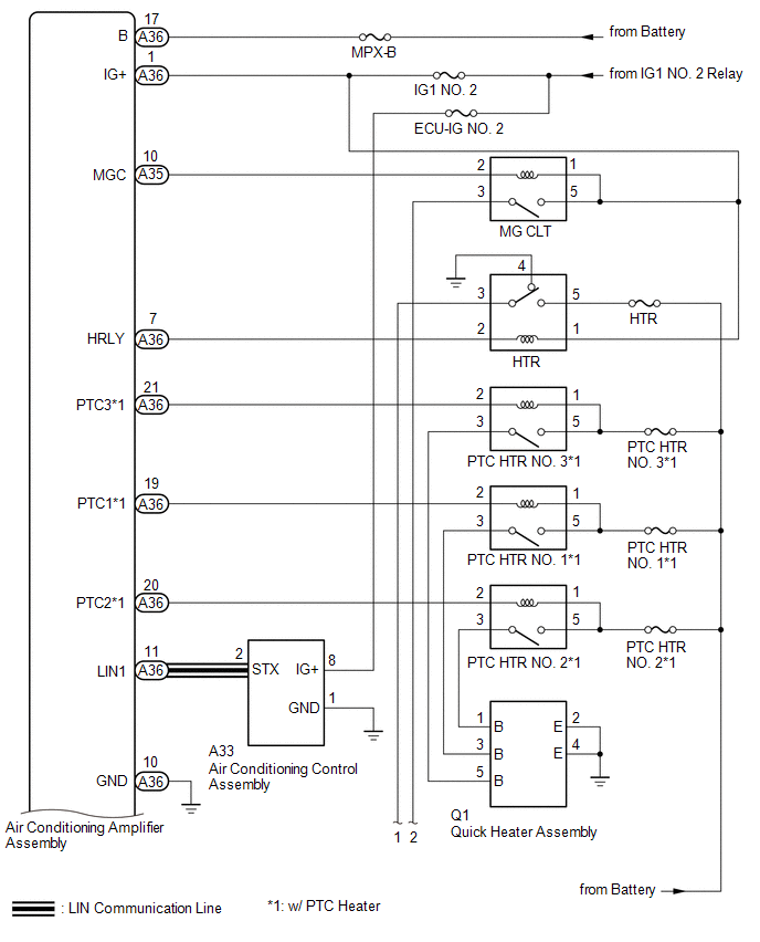
Air Conditioning Compressor Magnetic Clutch Circuit
DESCRIPTION
When the air conditioning amplifier assembly is turned on, a magnetic clutch
on signal is sent from the MGC terminal of the air conditioning amplifier assembly.
Then, the MG CLT relay turns on to operate the magnetic clutch assembly.
WIRING DIAGRAM
CAUTION / NOTICE / HINT
NO ...
Diagnostic Trouble Code Chart
DIAGNOSTIC TROUBLE CODE CHART
LANE DEPARTURE ALERT SYSTEM
DTC No.
Detection Item
Link
C1A47
Steering Angle Sensor
C1AA0
Front Camera Module Circuit
C1AA1
F ...
