Toyota Tacoma (2015-2018) Service Manual: Steering Pad Switch Circuit
DESCRIPTION
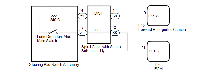
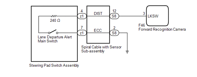
The forward recognition camera receives a lane departure alert switch signal from the steering pad switch assembly.
WIRING DIAGRAM
for 2TR-FE
for 2GR-FKS
CAUTION / NOTICE / HINT
NOTICE:
The vehicle is equipped with a Supplemental Restraint System (SRS) which includes components such as airbags. Before servicing (including removal or installation of parts), be sure to read the precaution for Supplemental Restraint System.
Click here .gif)
PROCEDURE
|
1. |
INSPECT STEERING PAD SWITCH ASSEMBLY |
(a) Remove the steering pad switch assembly.
Click here
(b) Inspect the steering pad switch assembly.
Click here
| NG | .gif) |
REPLACE STEERING PAD SWITCH ASSEMBLY |
|
.gif)
|
2. |
INSPECT SPIRAL CABLE WITH SENSOR SUB-ASSEMBLY |
(a) Remove the spiral cable with sensor sub-assembly.
Click here
(b) Inspect the spiral cable with sensor sub-assembly.
Click here
| NG | |
REPLACE SPIRAL CABLE WITH SENSOR SUB-ASSEMBLY |
|
|
3. |
CHECK HARNESS AND CONNECTOR (SPIRAL CABLE WITH SENSOR SUB-ASSEMBLY - FORWARD RECOGNITION CAMERA) |
(a) Disconnect the S8 spiral cable with sensor sub-assembly connector.
(b) Disconnect the F46 forward recognition camera connector.
(c) Measure the resistance according to the value(s) in the table below.
Standard Resistance:
|
Tester Connection |
Condition |
Specified Condition |
|---|---|---|
|
S8-12 (DIST) - F46-3 (LKSW) |
Always |
Below 1 Ω |
|
S8-12 (DIST) or F46-3 (LKSW) - Body ground |
Always |
10 kΩ or higher |
(d) Connect the F46 forward recognition camera connector.
(e) Connect the S8 spiral cable with sensor sub-assembly connector.
|
Result |
Proceed to |
|---|---|
|
OK (for 2TR-FE) |
A |
|
OK (for 2GR-FKS) |
B |
|
NG |
C |
| B | |
GO TO STEP 5 |
| C | |
REPAIR OR REPLACE HARNESS OR CONNECTOR |
|
|
4. |
CHECK HARNESS AND CONNECTOR (SPIRAL CABLE WITH SENSOR SUB-ASSEMBLY - ECM) |
(a) Disconnect the S8 spiral cable with sensor sub-assembly connector.
(b) Disconnect the E20 ECM connector.
(c) Measure the resistance according to the value(s) in the table below.
Standard Resistance:
|
Tester Connection |
Condition |
Specified Condition |
|---|---|---|
|
S8-2 (ECC) - E20-21 (ECCS) |
Always |
Below 1 Ω |
|
S8-2 (ECC) or E20-21 (ECCS) - Body ground |
Always |
10 kΩ or higher |
(d) Connect the S8 spiral cable with sensor sub-assembly connector.
(e) Connect the E20 ECM connector.
| OK | |
PROCEED TO NEXT SUSPECTED AREA SHOWN IN PROBLEM SYMPTOMS TABLE |
| NG | |
REPAIR OR REPLACE HARNESS OR CONNECTOR |
|
5. |
CHECK HARNESS AND CONNECTOR (SPIRAL CABLE WITH SENSOR SUB-ASSEMBLY - BODY GROUND) |
(a) Disconnect the S8 spiral cable with sensor sub-assembly connector.
(b) Measure the resistance according to the value(s) in the table below.
Standard Resistance:
|
Tester Connection |
Condition |
Specified Condition |
|---|---|---|
|
S8-2 (ECC) - Body ground |
Always |
Below 1 Ω |
(c) Connect the S8 spiral cable sub-assembly connector.
| OK | |
PROCEED TO NEXT SUSPECTED AREA SHOWN IN PROBLEM SYMPTOMS TABLE |
| NG | |
REPAIR OR REPLACE HARNESS OR CONNECTOR |
 Vehicle Speed Tolerance Malfunction (C1AA2)
DESCRIPTION
The forward recognition camera receives vehicle speed tolerance signals from
the combination meter assembly. If the combination meter assembly detects a vehicle
speed tolerance malfun ...
 Indicator Circuit
DESCRIPTION
The forward recognition camera sends indicator illumination request signals to
the combination meter assembly via CAN communication.
CAUTION / NOTICE / HINT
NOTICE:
When replacing th ...
Other materials:
Parts Location
PARTS LOCATION
ILLUSTRATION
ILLUSTRATION
ILLUSTRATION
ILLUSTRATION
...
Removal
REMOVAL
CAUTION / NOTICE / HINT
Text in Illustration
*a
Object Exceeding Weight Limit of Transmission Jack
Be sure to perform this procedure with several people as the rear differential
carrier assembly is very heavy.
Be sure to follow the procedure ...
Steering Angle Sensor Zero Point Malfunction (C1290)
DESCRIPTION
The skid control ECU (master cylinder solenoid) acquires steering angle sensor
zero point every time the ignition switch is turned to ON and the vehicle is driven
at 35 km/h (22 mph) or more for approximately 5 seconds. The ECU also stores the
previous zero point.
If the front wh ...
