Toyota Tacoma (2015-2018) Service Manual: Removal
REMOVAL
PROCEDURE
1. REMOVE NO. 2 ENGINE UNDER COVER SUB-ASSEMBLY (w/ Off Road Package)
2. REMOVE NO. 1 ENGINE UNDER COVER SUB-ASSEMBLY
3. DRAIN ENGINE COOLANT
.gif)
4. REMOVE V-BANK COVER SUB-ASSEMBLY
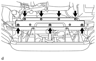
5. REMOVE RADIATOR SUPPORT TO FRAME SEAL
|
(a) Remove the 7 clips and radiator support to frame seal. |
|
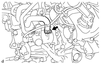
6. DISCONNECT NO. 2 RADIATOR HOSE
|
(a) Slide the hose clip and disconnect the No. 2 radiator hose from the water inlet with thermostat sub-assembly. |
|
.png)
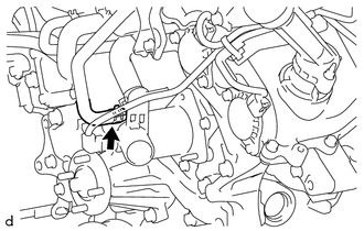
7. DISCONNECT NO. 7 WATER BY-PASS HOSE (w/ Oil Cooler)
|
(a) Slide the hose clip and disconnect the No. 7 water by-pass hose from the water inlet with thermostat sub-assembly. |
|
8. DISCONNECT NO. 4 WATER BY-PASS HOSE
|
(a) Slide the hose clip and disconnect the No. 4 water by-pass hose from the water inlet with thermostat sub-assembly. |
|
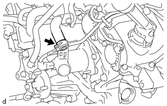
9. DISCONNECT NO. 3 WATER BY-PASS HOSE
|
(a) Slide the hose clip and disconnect the No. 3 water by-pass hose from the water inlet with thermostat sub-assembly. |
|
10. REMOVE WATER INLET WITH THERMOSTAT SUB-ASSEMBLY
HINT:
If the thermostat was not installed, cooling efficiency would decrease. Even if the engine tends to overheat, do not remove the thermostat.
|
(a) Disconnect the connector from the water inlet with thermostat sub-assembly. |
|
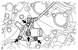
(b) Disengage the clamp to separate the wire harness.
(c) Remove the 2 bolts, nut and water inlet with thermostat sub-assembly from the timing chain cover assembly.
|
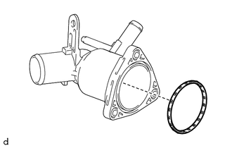
(d) Remove the gasket from the water inlet with thermostat sub-assembly. |
|
 Components
COMPONENTS
ILLUSTRATION
ILLUSTRATION
ILLUSTRATION
...
 Inspection
INSPECTION
PROCEDURE
1. INSPECT WATER INLET WITH THERMOSTAT SUB-ASSEMBLY
HINT:
The valve opening temperature is inscribed on the water inlet with thermostat
sub-assembly.
(a) Immerse the ther ...
Other materials:
Cellular Phone Registration Failure
PROCEDURE
1.
CHECK USAGE CONDITION
(a) Check that the vehicle and cellular phone meet the following conditions:
NOTICE:
If changing cellular phone settings, updating software, etc. is necessary, make
sure to obtain the permission of the customer before performin ...
Radio Receiver Power Source Circuit
DESCRIPTION
This is the power source circuit to operate the navigation receiver assembly.
WIRING DIAGRAM
CAUTION / NOTICE / HINT
NOTICE:
Inspect the fuses for circuits related to this system before performing
the following inspection procedure.
PROCEDURE
1.
...
Reassembly
REASSEMBLY
PROCEDURE
1. INSTALL OIL PUMP COVER
(a) Apply fresh engine oil to the drive and driven rotors.
(b) Place the drive and driven rotors into the timing chain cover assembly
with the marks facing the oil pump cover side.
Text in Illustration
*a
...
