Toyota Tacoma (2015-2018) Service Manual: Removal
REMOVAL
PROCEDURE
1. REMOVE FRONT WHEEL
2. REMOVE REAR WHEEL
3. REMOVE TIRE PRESSURE WARNING VALVE AND TRANSMITTER
(a) Remove the cap and valve core to release the air from the tire.
NOTICE:
Keep the removed cap and valve core.
(b) After ensuring that a sufficient amount of air has been released, remove the nut and washer used to secure the tire pressure warning valve and transmitter. Drop the tire pressure warning valve and transmitter with the grommet into the tire.
HINT:
The grommet may remain attached to the rim.
|
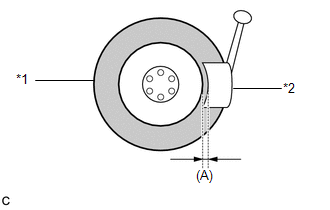
(c) After dropping the tire pressure warning valve and transmitter into the tire, disengage the bead using the shoe of a tire remover. Text in Illustration
NOTICE:
NOTICE: Be careful as the tire pressure warning valve and transmitter may become damaged due to interference between the sensor and tire bead. |
|
(d) Separate the upper bead.
(e) Take out the tire pressure warning valve and transmitter with the grommet from the tire and separate the lower bead.
(f) Remove the grommet from the tire pressure warning valve and transmitter.
 Installation
INSTALLATION
CAUTION / NOTICE / HINT
NOTICE:
Always use a new grommet and valve core when installing the tire pressure
warning valve and transmitter.
Check that the washer and nut a ...
 Vf2cm Transfer
...
Other materials:
Fail-safe Chart
FAIL-SAFE CHART
FAIL-SAFE FUNCTION
(a) When a malfunction occurs in the pre-collision system, a message will be
displayed on the multi-information display and the pre-collision system will be
disabled depending on the malfunction.
Warning Message
Cause
DTC No. ...
Wireless Charger Power Source Circuit
DESCRIPTION
This is the power source circuit to operate the mobile wireless charger cradle
assembly.
WIRING DIAGRAM
CAUTION / NOTICE / HINT
NOTICE:
Inspect the fuses for circuits related to this system before performing the following
inspection procedure.
PROCEDURE
1.
...
Components
COMPONENTS
ILLUSTRATION
ILLUSTRATION
ILLUSTRATION
ILLUSTRATION
ILLUSTRATION
*A
w/ Seat Heater System
-
-
*1
FRONT SEAT CUSHION HEATER ASSEMBLY
*2
FRONT SEATBACK HEATER ASSEMBLY
...
