Toyota Tacoma (2015-2018) Service Manual: Radio Receiver Power Source Circuit
DESCRIPTION
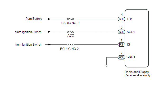
This is the power source circuit to operate the radio and display receiver assembly.
WIRING DIAGRAM
CAUTION / NOTICE / HINT
NOTICE:
- Inspect the fuses for circuits related to this system before performing the following inspection procedure.
PROCEDURE
|
1. |
CHECK HARNESS AND CONNECTOR (RADIO AND DISPLAY RECEIVER ASSEMBLY - BATTERY AND BODY GROUND) |
|
(a) Disconnect the radio and display receiver assembly connectors. |
|
(b) Measure the resistance according to the value(s) in the table below.
Standard Resistance:
|
Tester Connection |
Condition |
Specified Condition |
|---|---|---|
|
R30-7 (GND1) - Body ground |
Always |
Below 1 Ω |
(c) Measure the voltage according to the value(s) in the table below.
Standard Voltage:
|
Tester Connection |
Switch Condition |
Specified Condition |
|---|---|---|
|
R30-4 (+B1) - R30-7 (GND1) |
Always |
11 to 14 V |
|
R30-3 (ACC1) - R30-7 (GND1) |
Ignition switch ACC |
11 to 14 V |
|
R31-1 (IG) - R30-7 (GND1) |
Ignition switch ON |
11 to 14 V |
|
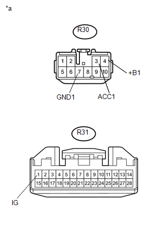
*a |
Front view of wire harness connector (to Radio and Display Receiver Assembly) |
| OK | .gif) |
PROCEED TO NEXT SUSPECTED AREA SHOWN IN PROBLEM SYMPTOMS TABLE |
| NG | |
REPAIR OR REPLACE HARNESS OR CONNECTOR |
 Microphone Circuit between Microphone and Radio Receiver
DESCRIPTION
The radio and display receiver assembly and telephone microphone assembly are
connected to each other using the microphone connection detection signal lines.
Using this circuit, the ra ...

Other materials:
Disassembly
DISASSEMBLY
CAUTION / NOTICE / HINT
HINT:
The procedure described below is for the LH side. Use the same procedure for
both the LH and RH sides, unless otherwise specified.
PROCEDURE
1. REMOVE REAR SEATBACK COVER
(a) Remove the 2 screws.
...
Check Bus 3 Line for Short to GND
DESCRIPTION
There may be a short circuit between one of the CAN bus lines and GND when there
is no resistance between terminal 6 (CA3H) of the central gateway ECU (network gateway
ECU) and terminal 4 (CG) of the DLC3, or terminal 21 (CA3L) of the central gateway
ECU (network gateway ECU) and ...
Cruise Control Switch Circuit
DESCRIPTION
This circuit sends signals to the ECM depending on the cruise control main switch
condition.
The battery supplies the positive (+) battery voltage to the cruise control main
switch. Then terminal CCS of the ECM receives the voltage as the signal according
to the switch condition. ...
