Toyota Tacoma (2015-2018) Service Manual: Open or Short Circuit in Back Camera Signal (C1622)
DESCRIPTION
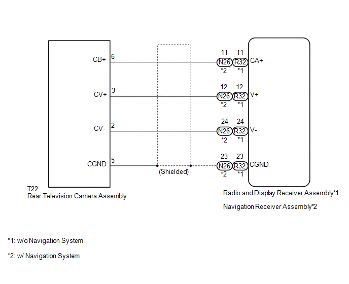
This DTC is stored if the radio and display receiver assembly*1 or navigation receiver assembly*2 judges as a result of its self check that the signals or signal lines between the radio and display receiver assembly*1 or navigation receiver assembly*2 and the rear television camera assembly are not normal.
|
DTC Code |
DTC Detection Condition |
Trouble Area |
|---|---|---|
|
C1622 |
Open or Short Circuit in rear television camera signal |
|
- *1: w/o Navigation System
- *2: w/ Navigation System
WIRING DIAGRAM
PROCEDURE
|
1. |
CHECK FOR DTC |
(a) Clear the DTCs (See page .gif) ).
).
(b) Check for DTCs (See page ).
|
Result |
Proceed to |
|---|---|
|
No DTC is output |
A |
|
DTC is output |
B |
| A | .gif) |
USE SIMULATION METHOD TO CHECK |
|
.gif)
|
2. |
CONFIRM MODEL |
(a) Choose the model to be inspected.
Result|
Result |
Proceed to |
|---|---|
|
w/o Navigation System |
A |
|
w/ Navigation System |
B |
| B | |
GO TO STEP 9 |
|
|
3. |
CHECK HARNESS AND CONNECTOR (RADIO AND DISPLAY RECEIVER ASSEMBLY - REAR TELEVISION CAMERA ASSEMBLY) |
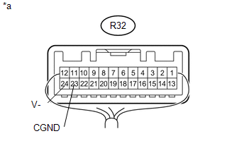
(a) Disconnect the R32 radio and display receiver assembly connector.
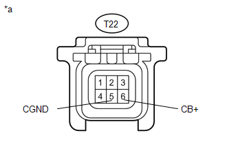
(b) Disconnect the T22 rear television camera assembly connector.
(c) Measure the resistance according to the value(s) in the table below.
Standard Resistance:
|
Tester Connection |
Condition |
Specified Condition |
|---|---|---|
|
R32-11 (CA+) - T22-6 (CB+) |
Always |
Below 1 Ω |
|
R32-12 (V+) - T22-3 (CV+) |
Always |
Below 1 Ω |
|
R32-23 (CGND) - T22-5 (CGND) |
Always |
Below 1 Ω |
|
R32-24 (V-) - T22-2 (CV-) |
Always |
Below 1 Ω |
|
R32-11 (CA+) - Body ground |
Always |
10 kΩ or higher |
|
R32-12 (V+) - Body ground |
Always |
10 kΩ or higher |
|
R32-23 (CGND) - Body ground |
Always |
10 kΩ or higher |
|
N26-24 (V-) - Body ground |
Always |
10 kΩ or higher |
| NG | |
REPAIR OR REPLACE HARNESS OR CONNECTOR |
|
|
4. |
CHECK RADIO AND DISPLAY RECEIVER ASSEMBLY |
|
(a) Measure the resistance according to the value(s) in the table below. Standard Resistance:
|
|
| NG | |
REPLACE RADIO AND DISPLAY RECEIVER ASSEMBLY |
|
|
5. |
CHECK RADIO AND DISPLAY RECEIVER ASSEMBLY |
|
(a) Disconnect the rear television camera assembly connector. |
|
(b) Measure the voltage according to the value(s) in the table below.
Standard Voltage:
|
Tester Connection |
Switch Condition |
Specified Condition |
|---|---|---|
|
T22-6 (CB+) - T22-5 (CGND) |
Ignition switch ACC |
5.5 to 7.05 V |
|
*a |
Front view of wire harness connector (to Rear Television Camera Assembly) |
| NG | |
REPLACE RADIO AND DISPLAY RECEIVER ASSEMBLY |
|
|
6. |
CHECK REAR TELEVISION CAMERA ASSEMBLY |
(a) Using an oscilloscope, check the waveform.
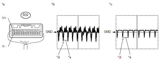 Text in Illustration
|
*a |
Component with harness connected (Radio and Display Receiver Assembly) |
*b |
Waveform 1 |
|
*c |
Waveform 2 |
*d |
Synchronized Signal |
|
*e |
Video Waveform |
- |
- |
|
Item |
Content |
|---|---|
|
Tester Connection |
R32-12 (V+) - R32-24 (V-) |
|
Tool Setting |
0.2 V/DIV., 50 ÎĽs/DIV. |
|
Condition |
|
OK:
Waveform is as shown in illustration.
HINT:
The video waveform changes according to the image sent by the rear television camera assembly.
| OK | |
USE SIMULATION METHOD TO CHECK |
|
|
7. |
REPLACE REAR TELEVISION CAMERA ASSEMBLY |
(a) Replace the rear television camera assembly with a new or normally functioning
one (See page ).
|
|
8. |
CHECK FOR DTC |
(a) Clear the DTCs (See page ).
(b) Check for DTCs (See page ).
OK:
No DTCs are output.
| OK | |
END (REAR TELEVISION CAMERA ASSEMBLY WAS DEFECTIVE) |
| NG | |
REPLACE RADIO AND DISPLAY RECEIVER ASSEMBLY |
|
9. |
CHECK HARNESS AND CONNECTOR (NAVIGATION RECEIVER ASSEMBLY - REAR TELEVISIONCAMERA ASSEMBLY) |
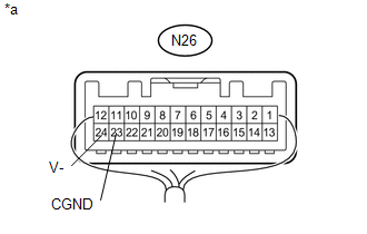
(a) Disconnect the N26 navigation receiver assembly connector.
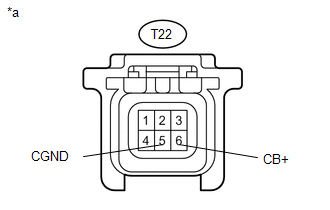
(b) Disconnect the T22 rear television camera assembly connector.
(c) Measure the resistance according to the value(s) in the table below.
Standard Resistance:
|
Tester Connection |
Condition |
Specified Condition |
|---|---|---|
|
N26-11 (CA+) - T22-6 (CB+) |
Always |
Below 1 Ω |
|
N26-12 (V+) - T22-3 (CV+) |
Always |
Below 1 Ω |
|
N26-23 (CGND) - T22-5 (CGND) |
Always |
Below 1 Ω |
|
N26-24 (V-) - T22-2 (CV-) |
Always |
Below 1 Ω |
|
N26-11 (CA+) - Body ground |
Always |
10 kΩ or higher |
|
N26-12 (V+) - Body ground |
Always |
10 kΩ or higher |
|
N26-23 (CGND) - Body ground |
Always |
10 kΩ or higher |
|
N26-24 (V-) - Body ground |
Always |
10 kΩ or higher |
| NG | |
REPAIR OR REPLACE HARNESS OR CONNECTOR |
|
|
10. |
CHECK NAVIGATION RECEIVER ASSEMBLY |
|
(a) Measure the resistance according to the value(s) in the table below. Standard Resistance:
|
|
| NG | |
REPLACE NAVIGATION RECEIVER ASSEMBLY |
|
|
11. |
CHECK NAVIGATION RECEIVER ASSEMBLY |
|
(a) Disconnect the rear television camera assembly connector. |
|
(b) Measure the voltage according to the value(s) in the table below.
Standard Voltage:
|
Tester Connection |
Switch Condition |
Specified Condition |
|---|---|---|
|
T22-6 (CB+) - T22-5 (CGND) |
Ignition switch ACC |
5.5 to 7.05 V |
|
*a |
Front view of wire harness connector (to Rear Television Camera Assembly) |
| NG | |
REPLACE NAVIGATION RECEIVER ASSEMBLY |
|
|
12. |
CHECK REAR TELEVISION CAMERA ASSEMBLY |
(a) Using an oscilloscope, check the waveform.
 Text in Illustration
|
*a |
Component with harness connected (Navigation Receiver Assembly) |
*b |
Waveform 1 |
|
*c |
Waveform 2 |
*d |
Synchronized Signal |
|
*e |
Video Waveform |
- |
- |
|
Item |
Content |
|---|---|
|
Tester Connection |
N26-12 (V+) - N26-24 (V-) |
|
Tool Setting |
0.2 V/DIV., 50 ÎĽs/DIV. |
|
Condition |
|
OK:
Waveform is as shown in illustration.
HINT:
The video waveform changes according to the image sent by the rear television camera assembly.
| OK | |
USE SIMULATION METHOD TO CHECK |
|
|
13. |
REPLACE REAR TELEVISION CAMERA ASSEMBLY |
(a) Replace the rear television camera assembly with a new or normally functioning
one (See page ).
|
|
14. |
CHECK FOR DTC |
(a) Clear the DTCs (See page ).
(b) Check for DTCs (See page ).
OK:
No DTCs are output.
| OK | |
END (REAR TELEVISION CAMERA ASSEMBLY WAS DEFECTIVE) |
| NG | |
REPLACE NAVIGATION RECEIVER ASSEMBLY |
 Dtc Check / Clear
DTC CHECK / CLEAR
HINT:
Refer to Audio and Visual System (w/o Navigation System) (See page
).
Refer to Navigation System (w/ Navigation System) (See page
).
...
 Reverse Signal Circuit
DESCRIPTION
The radio and display receiver assembly*1 or navigation receiver assembly*2 receives
a reverse signal from the park/neutral position switch*3 or the back-up light switch
assembly*4.
...
Other materials:
Installation
INSTALLATION
CAUTION / NOTICE / HINT
HINT:
Use the same procedure for the RH side and LH side.
The following procedure is for the LH side.
PROCEDURE
1. INSTALL REAR DOOR GLASS OUTER WEATHERSTRIP
(a) Engage the 6 claws to install the rear door glass outer weatherstr ...
Diagnostic Trouble Code Chart
DIAGNOSTIC TROUBLE CODE CHART
Differential System (w/ Differential Lock)
DTC Code
Detection Item
See page
P163B
4WD ECU Malfunction
P17BB
Rear Differential Lock Position SW Stuck OFF
...
Side Turn Signal Light Assembly
Components
COMPONENTS
ILLUSTRATION
Removal
REMOVAL
CAUTION / NOTICE / HINT
HINT:
Use the same procedure for both the RH and LH sides.
The procedure described below is for the LH side.
PROCEDURE
1. REMOVE OUTER REAR VIEW MIRROR ASSEMBLY
(See page )
2. REMOVE OUTER ...
