Toyota Tacoma (2015-2018) Service Manual: Installation
INSTALLATION
PROCEDURE
1. INSTALL FUEL SUCTION TUBE SET GASKET
(a) Ensure gasket groove is clean and free of foreign particles.
|
(b) Install a new gasket onto the fuel tank. |
|
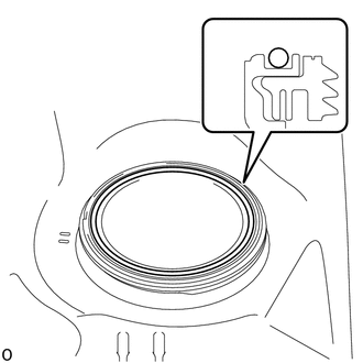
(c) Make sure that the gasket sits in the groove.
2. INSTALL FUEL SUCTION TUBE WITH PUMP AND GAUGE ASSEMBLY
|
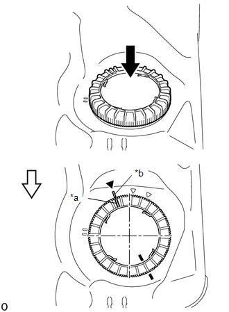
(a) Align the protrusion of the fuel suction tube with pump and gauge assembly with the cutout of the fuel tank assembly to install the fuel suction tube with pump and gauge assembly. NOTICE: Be careful not to bend the arm of the fuel sender gauge assembly. |
|
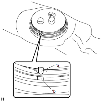
3. INSTALL FUEL PUMP GAUGE RETAINER
(a) Place a paint mark on the fuel suction tube with pump and gauge assembly as shown in the illustration.
.png)
|
*a |
Paint Mark |
.png) |
Front Side of Vehicle |
HINT:
Perform this step only when replacing the fuel suction tube with pump and gauge assembly.
(b) Align the start of the threads of a new fuel pump gauge retainer with the start of threads mark while pushing down the fuel suction tube with pump and gauge assembly, attach the fuel pump gauge retainer.
|
*a |
Start of Threads of the Fuel Pump Gauge Retainer |
|
*b |
Start of Threads of the Fuel Tank Assembly |
|
|
Press down |
.png) |
Front Side of Vehicle |
(c) Install SST to the fuel pump gauge retainer.
|
(1) Set 4 SST (claw set) to the fuel pump gauge retainer. SST: 09808-14031 09808-01080 09808-01090 09808-01100 NOTICE:
|
|
.png)
(2) Push SST (claw set) against the fuel pump gauge retainer and tighten SST (bolt).
.png)
|
*1 |
Fuel Pump Gauge Retainer |
|
*a |
SST (Claw Set) |
|
*b |
Hook |
|
|
Push |
|
|
SST (Bolt) |
(3) Temporarily install SST (plate) to SST (claw set) with 4 SST (bolt).
SST: 09808-14031
09808-01030
09808-01090
.png)
|
*a |
SST (Plate) |
|
*b |
SST (Claw Set) |
|
|
SST (Bolt) |
(4) Adjust the position of SST (claw set) so that the hole in SST (plate) for installing SST (handle) is in the center of the fuel pump gauge retainer.
.png)
|
*a |
Center Point of Fuel Pump Gauge Retainer |
|
*b |
SST (Plate) |
|
|
Front Side of Vehicle |
(5) Press SST (claw set) against the rib of the fuel pump gauge retainer and tighten SST (bolt).
.png)
|
*1 |
Fuel Pump Gauge Retainer |
|
*a |
SST (Plate) |
|
*b |
SST (Claw Set) |
|
*c |
SST (Bolt) |
|
|
Press |
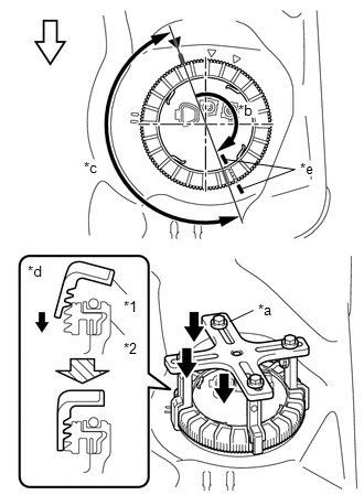
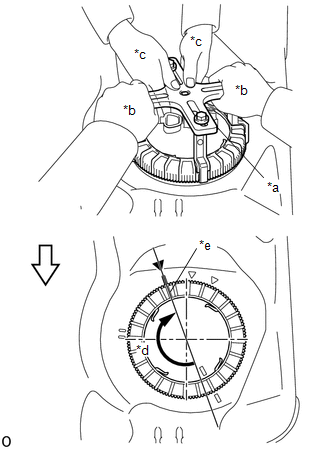
(d) While pressing down on the fuel suction tube with pump and gauge assembly, have another person firmly press the fuel pump gauge retainer against the threads of the fuel tank assembly, and tighten the fuel pump gauge retainer by approximately 180°.
|
*1 |
Fuel Pump Gauge Retainer |
|
*2 |
Fuel Tank Assembly |
|
*a |
SST (Plate) |
|
*b |
Tighten approximately 180° |
|
*c |
Fuel pump gauge retainer rises up |
|
*d |
Cross Section |
|
*e |
Paint Mark |
|
|
Press quickly and firmly |
|
|
Front Side of Vehicle |
NOTICE:
- To prevent damage to parts, do not turn SST too vigorously.
- Do not turn the fuel pump gauge retainer if the paint marks become misaligned.
(e) Quickly and firmly press down on the part of the fuel pump gauge retainer closest to the front of the vehicle to keep it from rising up.
HINT:
- If the fuel pump gauge retainer cannot be properly pressed down due to the position of SST, set SST in a different position.
- When fully pressing down the fuel pump gauge retainer, there will be a sound or tactile sensation of parts contacting each other, and at this point the fuel suction tube with pump and gauge assembly will stop rising up.
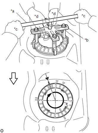
(f) While pressing down on the fuel suction tube with pump and gauge assembly, have another person slowly tighten the fuel pump gauge retainer by approximately 180°.
|
*a |
SST (Plate) |
|
*b |
One Person in Charge of Tightening |
|
*c |
One Person in Charge of Pressing Down |
|
*d |
Tighten approximately 180° |
|
*e |
Fuel Pump Gauge Retainer Start of Threads Location |
|
|
Slowly Rotate |
|
|
Front Side of Vehicle |
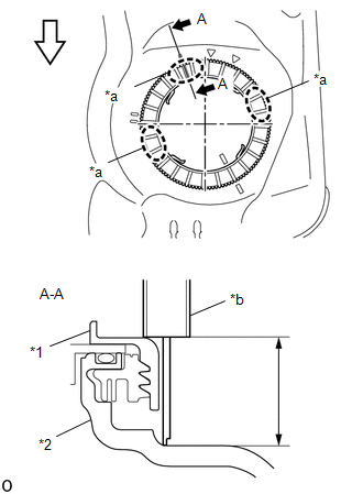
(g) Check the tightening status of the fuel pump gauge retainer.
(1) Using a vernier caliper, measure the distance from the fuel tank assembly to the upper surface of the fuel pump gauge retainer at 3 positions as shown in the illustration.
|
*1 |
Fuel Pump Gauge Retainer |
|
*2 |
Fuel Tank Assembly |
|
*a |
Measurement Position |
|
*b |
Vernier Caliper |
|
|
Front Side of Vehicle |
Standard:
Difference between the 3 measured values is 3 mm (0.118 in.) or less.
NOTICE:
If the difference between measurements is approximately 6 mm (0.236 in.), the threads are cross-threaded by 1 row (6 mm (0.236 in.)), so remove and reinstall the fuel pump gauge retainer.
(h) Install SST (handle) to SST (plate).
SST: 09808-14031
09808-01010
09808-01020
|
*a |
SST (Handle) |
|
*b |
SST (Plate) |
|
*c |
One Person in Charge of Tightening |
|
*d |
One Person in Charge of Pressing Down |
|
*e |
Tighten approximately 360° |
|
|
Slowly Rotate |
|
|
Front Side of Vehicle |
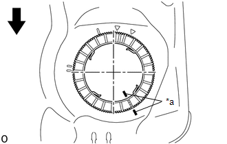
(i) While pressing down on the fuel suction tube with pump and gauge assembly, have another person use SST (handle) to slowly tighten the fuel pump gauge retainer approximately 360°.

|
*a |
SST (Handle) |
|
*b |
SST (Plate) |
|
*c |
Start of Threads of the Fuel Pump Gauge Retainer |
|
*d |
Fully Tightened Mark |
|
*e |
25 to 45° |
|
|
Tighten |
|
|
Front Side of Vehicle |
(j) Slowly tighten the fuel pump gauge retainer until it reaches the fully tightened mark that was copied onto the vehicle body.
(k) If the start mark does not reach 745°, confirm that no cross threading occurred by measuring the gap between the fuel pump gauge retainer and the fuel tank.
If cross threading occurred, replace the fuel pump gauge retainer and fuel suction tube set gasket.
(l) Put a mark on the fuel pump gauge retainer and the fuel tank with paint. This will be the evidence that the fuel pump gauge retainer has been removed.
|
*a |
Paint Mark |
|
|
Front Side of Vehicle |
4. CONNECT FUEL TANK MAIN TUBE SUB-ASSEMBLY
Click here .gif)
5. INSTALL FUEL TANK ASSEMBLY
Click here
 Inspection
INSPECTION
PROCEDURE
1. INSPECT FUEL PUMP
(a) Inspect the resistance of the fuel pump.
(1) Measure the resistance according to the value(s) in the table below.
Text in Illustration ...
 Reassembly
REASSEMBLY
CAUTION / NOTICE / HINT
NOTICE:
Do not try to remove the black nylon tube as it is welded to the fuel suction
tube assembly (See page
).
HINT:
Perform "Inspection After Repai ...
Other materials:
Data List / Active Test
DATA LIST / ACTIVE TEST
1. READ DATA LIST
HINT:
Using the Techstream to read the Data List allows the values or states of switches,
sensors, actuators and other items to be read without removing any parts. This non-intrusive
inspection can be very useful because intermittent conditions or sig ...
Pressure Control Solenoid "B" Performance (Shift Solenoid Valve SL2) (P0776)
SYSTEM DESCRIPTION
The ECM uses the vehicle speed signal and signals from the transmission revolution
sensors (NT, SP2) to detect the actual gear (1st, 2nd, 3rd, 4th, 5th or 6th gear).
The ECM compares the actual gear with the shift schedule in the ECM memory to
detect mechanical problems of t ...
CD cannot be Ejected
PROCEDURE
1.
CHECK OPERATION
(a) Press the disc eject switch of the radio and display receiver assembly for
5 seconds or more and check that the CD is ejected.
OK:
CD is ejected.
NG
REPLACE RADIO AND DISPLAY RECEIVER ASSEMBLY
...
