Toyota Tacoma (2015-2018) Service Manual: Front Differential Oil Temperature Sensor Circuit Low (P17C7)
DESCRIPTION
This DTC is output when a short to ground in the oil temperature sensor is detected.
|
DTC No. |
Detection Item |
DTC Detection Condition |
Trouble Area |
|---|---|---|---|
|
P17C7 |
Front Differential Oil Temperature Sensor Circuit Low |
|
|
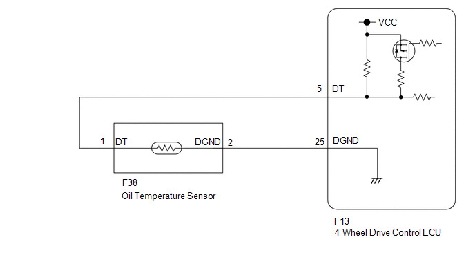
WIRING DIAGRAM
PROCEDURE
|
1. |
CHECK HARNESS AND CONNECTOR (4 WHEEL DRIVE CONTROL ECU AND OIL TEMPERATURE SENSOR - BODY GROUND) |
(a) Disconnect the F13 4 wheel drive control ECU connector.
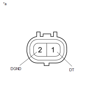
(b) Disconnect the F38 oil temperature sensor connector.
(c) Measure the resistance according to the value(s) in the table below.
Standard Resistance:
|
Tester Connection |
Condition |
Specified Condition |
|---|---|---|
|
F13-5 (DT) or F38-1 (DT) - Body ground |
Always |
10 kΩ or higher |
|
F13-25 (DGND) or F38-2 (DGND) - Body ground |
Always |
10 kΩ or higher |
| NG | .gif) |
REPAIR OR REPLACE HARNESS OR CONNECTOR |
|
.gif)
|
2. |
INSPECT OIL TEMPERATURE SENSOR |
(a) Disconnect the F38 oil temperature sensor connector.
|
(b) Measure the resistance according to the value(s) in the table below. Standard Resistance:
|
|
| OK | |
REPLACE 4 WHEEL DRIVE CONTROL ECU |
| NG | |
REPLACE OIL TEMPERATURE SENSOR |
 Diagnostic Trouble Code Chart
DIAGNOSTIC TROUBLE CODE CHART
TOUCH SELECT 2-4 AND HIGH-LOW SYSTEM
DTC Code
Detection Item
See page
P163B
4WD ECU Malfunction
...
 Front Differential Oil Temperature Sensor Circuit High (P17C8)
DESCRIPTION
This DTC is output when a short to B+ or open circuit in the oil temperature
sensor is detected.
DTC No.
Detection Item
DTC Detection Condition
...
Other materials:
Data List / Active Test
DATA LIST / ACTIVE TEST
NOTICE:
In the table below, the values listed under "Normal Condition" are reference
values. Do not depend solely on these reference values when deciding whether a part
is faulty or not.
HINT:
Using the Techstream to read the Data List allows the values or s ...
Removal
REMOVAL
PROCEDURE
1. REMOVE FUEL TANK ASSEMBLY
Click here
2. DISCONNECT FUEL TANK MAIN TUBE SUB-ASSEMBLY
Click here
3. REMOVE FUEL PUMP GAUGE RETAINER
NOTICE:
Before performing these procedures, first cover the connectors and tube joints
of the fuel suction tube with pump and gauge ass ...
Test Mode Procedure
TEST MODE PROCEDURE
1. TEST MODE (SIGNAL CHECK MODE) PROCEDURE
HINT:
When entering test mode (signal check mode), the tire pressure warning
ECU and receiver stores all the test mode (signal check mode) DTCs first.
After the tire pressure warning ECU and receiver completes the signa ...
