Toyota Tacoma (2015-2018) Service Manual: Front Airbag Sensor RH Circuit Malfunction (B1610/13)
DESCRIPTION
The front airbag sensor RH consists of parts such as the diagnostic circuit and the frontal detection sensor.
When the airbag sensor assembly receives signals from the frontal deceleration sensor, it determines whether or not the SRS should be activated.
DTC B1610/13 is set when a malfunction is detected in the front airbag sensor RH circuit.
|
DTC No. |
DTC Detecting Condition |
Trouble Areas |
|---|---|---|
|
B1610/13 |
|
|
WIRING DIAGRAM
.png)
CAUTION / NOTICE / HINT
NOTICE:
After turning the ignition switch off, waiting time may be required before disconnecting
the cable from the negative (-) battery terminal. Therefore, make sure to read the
disconnecting the cable from the negative (-) battery terminal notices before proceeding
with work (See page .gif) ).
).
PROCEDURE
|
1. |
CHECK CONNECTION OF CONNECTORS |
(a) Turn the ignition switch off.
(b) Disconnect the negative (-) terminal cable from the battery, and wait for at least 90 seconds.
(c) Check that the connectors are properly connected to the airbag sensor assembly and the front airbag sensor RH.
OK:
The connectors are properly connected.
| NG | .gif) |
CONNECT CONNECTORS |
|
.gif)
|
2. |
CHECK CONNECTOR |
(a) Check that the connectors (on the airbag sensor assembly side and front airbag
sensor RH side) are not damaged (See page ).
OK:
The connectors are not deformed or damaged.
| NG | |
REPLACE WIRE HARNESS |
|
|
3. |
CHECK FRONT AIRBAG SENSOR RH CIRCUIT (FOR OPEN) |
|
(a) Disconnect the connectors from the airbag sensor assembly and the front airbag sensor RH. |
|
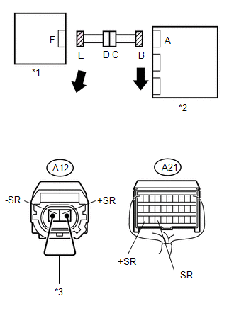
(b) Using a service wire, connect A12-2 (+SR) and A12-1 (-SR) of connector E.
NOTICE:
Do not forcibly insert the service wires into the terminals of the connector when connecting.
(c) Measure the resistance according to the value(s) in the table below.
Standard Resistance:
|
Tester Connection |
Condition |
Specified Condition |
|---|---|---|
|
A21-29 (+SR) - A21-27 (-SR) |
Always |
Below 1 Ω |
|
*1 |
Front Airbag Sensor RH |
|
*2 |
Airbag Sensor Assembly |
|
*3 |
Service Wire |
| NG | |
GO TO STEP 9 |
|
|
4. |
CHECK FRONT AIRBAG SENSOR RH CIRCUIT (FOR SHORT) |
|
(a) Disconnect the service wire from connector E. |
|
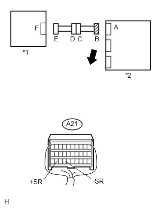
(b) Measure the resistance according to the value(s) in the table below.
Standard Resistance:
|
Tester Connection |
Condition |
Specified Condition |
|---|---|---|
|
A21-29 (+SR) - A21-27 (-SR) |
Always |
1 MΩ or higher |
|
*1 |
Front Airbag Sensor RH |
|
*2 |
Airbag Sensor Assembly |
| NG | |
GO TO STEP 10 |
|
|
5. |
CHECK FRONT AIRBAG SENSOR RH CIRCUIT (TO B+) |
|
(a) Connect the negative (-) terminal cable to the battery, and wait for at least 2 seconds. |
|
(b) Turn the ignition switch to ON.
(c) Measure the voltage according to the value(s) in the table below.
Standard Voltage:
|
Tester Connection |
Switch Condition |
Specified Condition |
|---|---|---|
|
A21-29 (+SR) - Body ground |
Ignition switch ON |
Below 1 V |
|
A21-27 (-SR) - Body ground |
Ignition switch ON |
Below 1 V |
|
*1 |
Front Airbag Sensor RH |
|
*2 |
Airbag Sensor Assembly |
| NG | |
GO TO STEP 11 |
|
|
6. |
CHECK FRONT AIRBAG SENSOR RH CIRCUIT (TO GROUND) |
|
(a) Turn the ignition switch off. |
|
(b) Disconnect the negative (-) terminal cable from the battery, and wait for at least 90 seconds.
(c) Measure the resistance according to the value(s) in the table below.
Standard Resistance:
|
Tester Connection |
Condition |
Specified Condition |
|---|---|---|
|
A21-29 (+SR) - Body ground |
Always |
1 MΩ or higher |
|
A21-27 (-SR) - Body ground |
Always |
1 MΩ or higher |
|
*1 |
Front Airbag Sensor RH |
|
*2 |
Airbag Sensor Assembly |
| NG | |
GO TO STEP 12 |
|
|
7. |
CHECK FRONT AIRBAG SENSOR RH |
(a) Connect the connectors to the airbag sensor assembly.
(b) Interchange the front airbag sensor RH with the front airbag sensor LH and connect the connectors to them.
(c) Connect the negative (-) terminal cable to the battery, and wait for at least 2 seconds.
(d) Turn the ignition switch to ON, and wait for at least 60 seconds.
(e) Clear any DTCs stored in the memory (See page
).
(f) Turn the ignition switch off.
(g) Turn the ignition switch to ON, and wait for at least 60 seconds.
(h) Check for DTCs (See page ).
|
Result |
Proceed to |
|---|---|
|
DTC B1610/13 is output. |
A |
|
DTC B1615/14 is output. |
B |
|
Neither DTC B1610/13 nor B1615/14 is output. |
C |
| B | |
REPLACE FRONT AIRBAG SENSOR RH |
| C | |
USE SIMULATION METHOD TO CHECK |
|
|
8. |
REPLACE AIRBAG SENSOR ASSEMBLY |
(a) Turn the ignition switch off.
(b) Disconnect the negative (-) terminal cable from the battery, and wait for at least 90 seconds.
(c) Replace the airbag sensor assembly (See page
).
HINT:
Perform the inspection using parts from a normal vehicle when possible.
(d) Connect the connectors to the airbag sensor assembly.
(e) Connect the negative (-) terminal cable to the battery, and wait for at least 2 seconds.
(f) Turn the ignition switch to ON, and wait for at least 60 seconds.
(g) Clear any DTCs stored in the memory (See page
).
(h) Turn the ignition switch off.
(i) Turn the ignition switch to ON, and wait for at least 60 seconds.
(j) Check for DTCs (See page ).
OK:
DTC B1610/13 is not output.
HINT:
DTCs other than B1610/13 may be output at this time, but they are not related to this check.
| OK | |
END |
| NG | |
REPLACE FRONT AIRBAG SENSOR RH |
|
9. |
CHECK ENGINE ROOM MAIN WIRE (FOR OPEN) |
|
(a) Disconnect the engine room main wire connector from the instrument panel wire. |
|
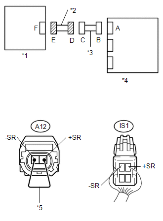
HINT:
The service wire has already been inserted into connector E.
(b) Measure the resistance according to the value(s) in the table below.
Standard Resistance:
|
Tester Connection |
Condition |
Specified Condition |
|---|---|---|
|
IS1 -1 (-SR) - IS1-2 (+SR) |
Always |
Below 1 Ω |
|
*1 |
Front Airbag Sensor RH |
|
*2 |
Engine Room Main Wire |
|
*3 |
Instrument Panel Wire |
|
*4 |
Airbag Sensor Assembly |
|
*5 |
Service Wire |
| OK | |
REPLACE INSTRUMENT PANEL WIRE |
| NG | |
REPLACE ENGINE ROOM MAIN WIRE |
|
10. |
CHECK ENGINE ROOM MAIN WIRE (FOR SHORT) |
|
(a) Disconnect the engine room main wire connector from the instrument panel wire. |
|
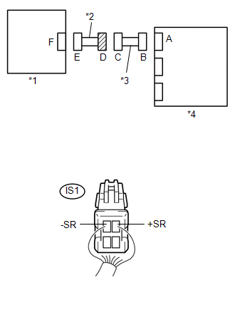
(b) Measure the resistance according to the value(s) in the table below.
Standard Resistance:
|
Tester Connection |
Condition |
Specified Condition |
|---|---|---|
|
IS1 -1 (-SR) - IS1-2 (+SR) |
Always |
1 MΩ or higher |
|
*1 |
Front Airbag Sensor RH |
|
*2 |
Engine Room Main Wire |
|
*3 |
Instrument Panel Wire |
|
*4 |
Airbag Sensor Assembly |
| OK | |
REPLACE INSTRUMENT PANEL WIRE |
| NG | |
REPLACE ENGINE ROOM MAIN WIRE |
|
11. |
CHECK ENGINE ROOM MAIN WIRE (TO B+) |
|
(a) Turn the ignition switch off. |
|
(b) Disconnect the negative (-) terminal cable from the battery, and wait for at least 90 seconds.
(c) Disconnect the engine room main wire connector from the instrument panel wire.
(d) Connect the negative (-) terminal cable to the battery, and wait for at least 2 seconds.
(e) Turn the ignition switch to ON.
(f) Measure the voltage according to the value(s) in the table below.
Standard Voltage:
|
Tester Connection |
Switch Condition |
Specified Condition |
|---|---|---|
|
IS1 -1 (-SR) - Body ground |
Ignition switch ON |
Below 1 V |
|
IS1-2 (+SR) - Body ground |
Ignition switch ON |
Below 1 V |
|
*1 |
Front Airbag Sensor RH |
|
*2 |
Engine Room Main Wire |
|
*3 |
Instrument Panel Wire |
|
*4 |
Airbag Sensor Assembly |
| OK | |
REPLACE INSTRUMENT PANEL WIRE |
| NG | |
REPLACE ENGINE ROOM MAIN WIRE |
|
12. |
CHECK ENGINE ROOM MAIN WIRE (TO GROUND) |
|
(a) Disconnect the engine room main wire connector from the instrument panel wire. |
|
(b) Measure the resistance according to the value(s) in the table below.
Standard Resistance:
|
Tester Connection |
Condition |
Specified Condition |
|---|---|---|
|
IS1 -1 (-SR) - Body ground |
Always |
1 MΩ or higher |
|
IS1-2 (+SR) - Body ground |
Always |
1 MΩ or higher |
|
*1 |
Front Airbag Sensor RH |
|
*2 |
Engine Room Main Wire |
|
*3 |
Instrument Panel Wire |
|
*4 |
Airbag Sensor Assembly |
| OK | |
REPLACE INSTRUMENT PANEL WIRE |
| NG | |
REPLACE ENGINE ROOM MAIN WIRE |
 Side Airbag Sensor RH Circuit Malfunction (B1620/21)
DESCRIPTION
The side airbag sensor assembly RH consists of parts such as the safing sensor,
the diagnostic circuit and the lateral deceleration sensor.
When the airbag sensor assembly receives sig ...
 SRS Warning Light does not Come ON
DESCRIPTION
See page .
WIRING DIAGRAM
See page .
CAUTION / NOTICE / HINT
NOTICE:
Inspect the fuses for circuits related to this system before performing
the following inspection pr ...
Other materials:
Front Camera Module Circuit (C1AA0)
DESCRIPTION
When an internal malfunction is detected in the forward recognition camera, DTC
C1AA0 is stored.
DTC No.
Detection Item
DTC Detection Condition
Trouble Area
C1AA0
Front Camera Module Circuit
3 seconds ...
On-vehicle Inspection
ON-VEHICLE INSPECTION
PROCEDURE
1. INSPECT BRAKE PEDAL HEIGHT
(a) Check the brake pedal height.
Pedal height from dash panel:
Type
Pedal Height
Automatic transmission
164.4 to 174.4 mm (6.473 to 6.866 in.)
Manual transmission ...
Sound of Portable Player cannot be Heard from Speakers or Sound is Low
PROCEDURE
1.
CHECK PORTABLE PLAYER SETTINGS
(a) Check the portable player settings.
(1) Check that the volume is not set to "0".
(2) Check that the mute is off.
(b) Check that the sound of the portable player can be heard from the speakers.
OK:
Sound ...
