Toyota Tacoma (2015-2018) Service Manual: Engine Immobiliser System Circuit Short to Battery (B279A12)
DESCRIPTION
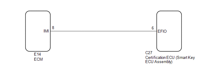
When the communication line (IMI - EFIO) between the ECM and certification ECU (smart key ECU assembly) is stuck high, the ECM stores this DTC.
|
DTC Code |
DTC Detection Condition |
Trouble Area |
DTC Output Confirmation Operation |
|---|---|---|---|
|
B279A12 |
The communication line (IMI - EFIO) between the ECM and certification ECU (smart key ECU assembly) is stuck high (1 trip detection logic*1). |
|
Turn the engine switch on (IG) and wait 6 seconds. |
- *1: Only output while a malfunction is present.
|
Vehicle Condition when Malfunction Detected |
Fail-safe Operation when Malfunction Detected |
|---|---|
|
Engine cannot be started (initial ignition occurs and engine cranks, then ignition stops) |
Engine cannot be started |
|
DTC Code |
Data List and Active Test |
|---|---|
|
B279A12 |
- |
WIRING DIAGRAM
CAUTION / NOTICE / HINT
NOTICE:
- When replacing the certification ECU (smart key ECU assembly), refer
to Registration (See page
.gif) ).
). - After performing repairs, perform the operation that fulfills the DTC output confirmation operation, and then confirm that no DTCs are output again.
HINT:
When DTC B279A12 and the certification ECU (smart key ECU assembly) DTC are output simultaneously, first perform troubleshooting for the certification ECU (smart key ECU assembly) DTC.
PROCEDURE
|
1. |
CLEAR DTC |
(a) Clear the DTCs (See page ).
|
.gif)
|
2. |
CHECK FOR DTC |
(a) Turn the engine switch on (IG) and wait 10 seconds.
(b) Check for DTCs (See page ).
|
Result |
Proceed to |
|---|---|
|
DTC or B279A12 is output |
A |
|
DTC or B279A12 and other DTCs are output |
B |
HINT:
If DTCs other than DTC B279A12 are output, troubleshoot those DTCs first.
| B | .gif) |
GO TO DIAGNOSTIC TROUBLE CODE CHART |
|
|
3. |
CHECK CONNECTION OF CONNECTOR |
(a) Turn the engine switch off.
(b) Check that the connectors are properly connected to the ECM and certification ECU (smart key ECU assembly).
OK:
Connectors are properly connected.
| NG | |
CONNECT CONNECTORS PROPERLY |
|
|
4. |
CHECK HARNESS AND CONNECTOR (CERTIFICATION ECU (SMART KEY ECU ASSEMBLY) - ECM) |
(a) Disconnect the C27 certification ECU (smart key ECU assembly) connector.
(b) Disconnect the E14 ECM connector.
(c) Measure the resistance according to the value(s) in the table below.
Standard Resistance:
|
Tester Connection |
Condition |
Specified Condition |
|---|---|---|
|
C27-6 (EFIO) - E14-8 (IMI) |
Always |
Below 1 Ω |
|
C27-6 (EFIO) or E14-8 (IMI) - Body ground |
Always |
10 kΩ or higher |
| NG | |
REPAIR OR REPLACE HARNESS OR CONNECTOR |
|
|
5. |
REPLACE CERTIFICATION ECU (SMART KEY ECU ASSEMBLY) |
(a) Replace the certification ECU (smart key ECU assembly) with a new one (See
page ).
|
|
6. |
REGISTER RECOGNITION CODES |
(a) Register the key (See page ).
|
|
7. |
REGISTER ECU COMMUNICATION ID |
(a) Register the ECU communication ID (See page
).
|
|
8. |
CLEAR DTC |
(a) Clear the DTCs (See page ).
|
|
9. |
CHECK FOR DTC |
(a) Check for DTCs (See page ).
HINT:
Before checking for DTCs, perform the "DTC Output Confirmation Operation" procedure.
OK:
DTC B279A12 is not output.
| OK | |
END (CERTIFICATION ECU (SMART KEY ECU ASSEMBLY) WAS DEFECTIVE) |
| NG | |
REPLACE ECM |
 Malfunction of ID-BOX Recognition (B278D)
DESCRIPTION
When the certification ECU (smart key ECU assembly) detects an input signal indicating
that the vehicle is equipped with an ID code box even though the ID code box is
not registered, ...
 Short to GND in Immobiliser System Power Source Circuit (B278A)
DESCRIPTION
When there is a short to GND in the power supply for the transponder key amplifier
of the engine switch, the certification ECU (smart key ECU assembly) stores this
DTC.
DT ...
Other materials:
Dtc Check / Clear
DTC CHECK / CLEAR
1. CHECK DTC
(a) Connect the Techstream to the DLC3.
(b) Turn the ignition switch to ON.
(c) Turn the Techstream on.
(d) Enter the following menus: Body Electrical / Sliding Roof / Trouble Codes.
(e) Check the details of the DTC(s) (See page
).
2. CLEAR DTC
(a) Connect th ...
Stop Light Relay Circuit (C1A4B)
DESCRIPTION
The skid control ECU (master cylinder solenoid)*1 or skid control ECU (brake
actuator assembly)*2 sends a stop light operation request signal to the stop light
relay (stop light switch assembly). If the skid control ECU (master cylinder solenoid)*1
or skid control ECU (brake actua ...
Theft Deterrent System is not Unset when Engine is Running
DESCRIPTION
The theft deterrent system is unset when the IG signal and engine speed signal
are input to the main body ECU (multiplex network body ECU) for 2 seconds or more
continuously.
The engine speed signal is sent from the ECM to the main body ECU (multiplex
network body ECU). For this ...
