Toyota Tacoma (2015-2018) Service Manual: Calibration
CALIBRATION
1. DESCRIPTION
(a) After replacing the VSC relevant components or performing "Front wheel alignment adjustment", clearing and reading the sensor calibration data are necessary.
(b) Follow the chart to perform calibration.
|
Replacing Parts |
Necessary Operations |
|---|---|
|
Skid Control ECU (Master Cylinder Solenoid) |
|
|
Yaw Rate and Acceleration Sensor (Airbag sensor assembly) |
|
|
Front Wheel Alignment |
|
2. CLEAR ZERO POINT CALIBRATION (for Using Techstream)
HINT:
After replacing the yaw rate and acceleration sensor (airbag sensor assembly), be sure to clear the zero point calibration data in the skid control ECU (master cylinder solenoid) and perform zero point calibration.
(a) Connect Techstream to the DLC3.
(b) Turn the ignition switch to ON.
(c) Operate Techstream to erase the DTCs.
(d) Perform zero point calibration of the yaw rate and acceleration sensor using Techstream.
3. PERFORM ZERO POINT CALIBRATION OF YAW RATE SENSOR AND ACCELERATION SENSOR (for Using Techstream)
HINT:
After replacing the yaw rate and acceleration sensor (airbag sensor assembly), be sure to clear the zero point calibration data in the skid control ECU (master cylinder solenoid) and perform zero point calibration.
NOTICE:
- While obtaining the zero point, do not vibrate the vehicle by tilting, moving or shaking it and keep it stationary. (Do not start the engine.)
- Be sure to do this on a level surface (with an inclination of less than 1°).
(a) Procedures for test mode.
(1) Turn the ignition switch to off.
(2) Check that the steering wheel is in the straight-ahead position.
(3) for Automatic transmission: Check that the shift lever is in P and apply the parking brake.
for Manual transmission: Check that the shift lever is in neutral and apply the parking brake.
NOTICE:
DTC C1210 and C1336 will be recorded if the shift lever is not in the P position.
(4) Connect Techstream to the DLC3.
(5) Turn the ignition switch to ON.
(6) Switch the ECU to test mode using Techstream. Enter the following menus: Chassis / ABS/VSC/TRAC / Utility / Signal Check.
(7) Keep the vehicle stationary on a level surface for 5 seconds or more.
(8) Check that the slip indicator light comes on for several seconds and then blinks in the test mode pattern (0.125 seconds on and 0.125 seconds off).
NOTICE:
The slip indicator light stay ON when obtaining the zero point.
HINT:
- If the slip indicator light does not blink, perform the zero point calibration again.
- The zero point calibration is performed only once after the system enters test mode.
- Calibration cannot be performed again until the stored data is cleared once.
(9) Turn the ignition switch to off.
4. PERFORM CRAWL CONTROL CALIBRATION (for Automatic transmission)
(a) Enter test mode.
(1) Turn the ignition switch off.
(2) Connect the Techstream to the DLC3.
(3) Turn the ignition switch to ON.
(4) Turn the Techstream on.
(5) Enter the following menus: Chassis / ABS/VSC/TRAC / Utility / Test Mode.
(b) Push the ON/OFF switch and check that the crawl indicator light is on while the switch is being pushed.
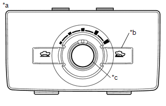 Text in Illustration
|
*a |
Drive Monitor Switch |
|
*b |
ON/OFF Switch |
|
*c |
Speed Selector Switch |
(c) Turn the ON/OFF switch off.
(d) Set the target vehicle speed to L (low) with the speed selector switch.
(e) Set the target vehicle speed to medium-low with the speed selector switch.
(f) Set the target vehicle speed to M (medium) with the speed selector switch.
(g) Set the target vehicle speed to medium-high with the speed selector switch.
(h) Set the target vehicle speed to H (high) with the speed selector switch.
(i) Set the target vehicle speed to L (low) with the speed selector switch.
HINT:
The speed selector status is displayed on the multi-information display.
(j) Turn the ignition switch off.
(k) Check if DTC C120A is output.
HINT:
If DTC C120A is not output, calibration was performed successfully.
 Check For Intermittent Problems
CHECK FOR INTERMITTENT PROBLEMS
1. DESCRIPTION
HINT:
A momentary interruption (open circuit) in the connectors and/or wire harness
between the sensors and ECUs can be detected through the ECU dat ...
 Problem Symptoms Table
PROBLEM SYMPTOMS TABLE
If a normal code is displayed during the DTC check but the problem still occurs,
check the circuits for each problem symptom in the order given in the table below
and proce ...
Other materials:
Inspection
INSPECTION
PROCEDURE
1. REMOVE SPIRAL CABLE SUB-ASSEMBLY WITH SENSOR
(a) If there are any defects as mentioned below, replace the spiral cable sub-assembly
with a new one:
Scratches, cracks, dents or chips on the connector or the spiral cable sub-assembly.
(b) Inspect the spiral ca ...
Removal
REMOVAL
CAUTION / NOTICE / HINT
CAUTION:
Some of these service operations affect the SRS airbag system. Read the precautionary
notices concerning the SRS airbag system before servicing (See page
).
HINT:
Use the same procedure for both the RH and LH sides.
The procedure describe ...
Driver Side Door ECU Communication Stop (B2321)
DESCRIPTION
This DTC is stored when LIN communication between the front power window regulator
motor assembly LH and main body ECU (multiplex network body ECU) stops for 10 seconds
or more.
DTC No.
DTC Detection Condition
Trouble Area
B2321
...
