Toyota Tacoma (2015-2018) Service Manual: AV Signal Stoppage (Low Battery Voltage) (B158F)
DESCRIPTION
This DTC is stored when a video or audio signal is interrupted due to battery voltage input to the navigation receiver assembly dropping temporarily.
|
DTC Code |
DTC Detection Condition |
Trouble Area |
|---|---|---|
|
B158F |
A video or audio signal is interrupted when the battery voltage drops. |
|
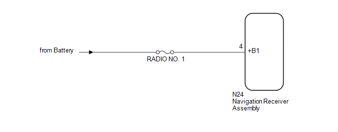
WIRING DIAGRAM
CAUTION / NOTICE / HINT
NOTICE:
Inspect the fuses for circuits related to this system before performing the following procedure.
PROCEDURE
|
1. |
CHECK VEHICLE SIGNAL (OPERATION CHECK) |
|
(a) Enter the "Vehicle Signal Check Mode" screen. Refer to Check Vehicle
Signal in Operation Check (See page |
|
.png)
(b) Check that the battery voltage.
Standard voltage:
11 to 14 V
HINT:
This display is updated once per second. As a result, it is normal for the display to lag behind the actual switch operation.
| NG | .gif) |
GO TO STEP 3 |
|
.gif)
|
2. |
CHECK FOR DTC |
(a) Clear the DTCs (See page .gif) ).
).
(b) Check for DTCs (See page ).
OK:
No DTCs are output.
| OK | |
USE SIMULATION METHOD TO CHECK |
| NG | |
REPLACE NAVIGATION RECEIVER ASSEMBLY |
|
3. |
CHECK HARNESS AND CONNECTOR (NAVIGATION RECEIVER ASSEMBLY POWER SOURCE) |
|
(a) Disconnect the navigation receiver assembly connector. |
|
(b) Measure the voltage according to the value(s) in the table below.
Standard Voltage:
|
Tester Connection |
Condition |
Specified Condition |
|---|---|---|
|
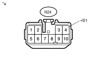
N24-4 (+B1) - Body ground |
Always |
11 to 14 V |
|
*a |
Front view of wire harness connector (to Navigation Receiver Assembly) |
| OK | |
REPLACE NAVIGATION RECEIVER ASSEMBLY |
| NG | |
REPAIR OR REPLACE HARNESS OR CONNECTOR |
 SD Card Communication Malfunction (B158C)
DESCRIPTION
The navigation receiver assembly stores this DTC when the SD card cannot be mounted
when inserted into the SD card slot.
DTC Code
DTC Detection Condition
...
 Stereo Component Amplifier Malfunction (B15A3)
DESCRIPTION
This DTC is stored when a malfunction occurs in the stereo component amplifier
assembly.
DTC No.
DTC Detection Condition
Trouble Area
...
Other materials:
Disassembly
DISASSEMBLY
PROCEDURE
1. REMOVE ROOM LIGHT BRACKET
(a) Disengage the guide to remove the room light bracket.
2. REMOVE SLIDING ROOF DRIVE GEAR SUB-ASSEMBLY
(a) Remove the 2 bolts and sliding roof drive gear sub-assembly.
...
Camshaft
Components
COMPONENTS
ILLUSTRATION
ILLUSTRATION
ILLUSTRATION
ILLUSTRATION
ILLUSTRATION
*1
FUEL PUMP ASSEMBLY
*2
FUEL PUMP LIFTER ASSEMBLY
*3
FUEL PUMP LIFTER GUIDE
*4
FUEL PUMP SPACER GAS ...
Removal
REMOVAL
PROCEDURE
1. REMOVE FUEL TANK ASSEMBLY
Click here
2. DISCONNECT CHARCOAL CANISTER FUEL HOSE
(a) Loosen the hose clip and disconnect the charcoal canister fuel hose.
3. DISCONNECT FUEL TANK VENT HOSE
(a) Push the fuel tank vent hos ...
